GF Signet 8550 ProcessPro Flow Transmitter User Manual
GF Signet Tools
Signet 8550-3 Flow Transmitter
Open-collector outputs, optically isolated:
• 50 mA max. sink, 30 VDC maximum pull-up voltage.
• Programmable for:
• High or Low setpoint with adjustable hysteresis
• Pulse proportional to rate or volume (max 300 pulses/min).
Environmental
• Operating temperature:
-10 to 70 °C (14 to 158 °F)
• Storage temperature:
-15 to 80 °C (5 to 176 °F)
• Relative humidity:
0 to 95%, non-condensing
• Maximum altitude:
2000 m (6562 ft)
• Insulation category:
II
• Pollution degree:
2
• Rating:
NEMA 4X/IP65 front
Standards and Approvals:
• CE, UL listed
• Manufactured under ISO 9001 for Quality, ISO 14001
for Environmental Management and OHSAS 18001 for
occupational health and safety.
China RoHS (Go to www.gfsignet.com for details)
General
Compatibility: Signet Flow Sensors (w/freq out)
Enclosure:
• Case:
PBT
Panel case gasket:
Neoprene
• Window:
Polyurethane coated polycarbonate
• Keypad:
Sealed 4-key silicone rubber
• Weight:
Approx. 325 g (12 oz.)
Display:
• Alphanumeric
2 x 16 LCD
• Update rate:
1 second
• Contrast:
User selected, 5 levels
• Accuracy:
± 0.5% of reading @ 25 ºC
• Thermal sensitivity shift: ± 0.005% of reading per ºC
Electrical
• Power:
12 to 24 VDC ±10%, regulated,
100 mA max.
Sensor Inputs:
• Range:
0.5 to 1500 Hz
• Sensor power:
2-wire: 0.5 mA @ 5 VDC ± 1%
3- or 4-wire: 20 mA @ 5 VDC ± 1%
• Optically isolated from current loop, short circuit protected
Current output:
• 4 to 20 mA, isolated, fully adjustable and reversible
• Max loop impedance:
50 Ω max. @ 12 V
325
Ω max. @ 18 V
600
Ω max. @ 24 V
• Update rate:
100 ms
• Accuracy:
± 0.03 mA
Flow1: 6.25 GPM
Flow2: 9.75 GPM
ENTER
Signet Flow
Transmitter
WARNING!
• Remove power to unit before wiring
input and output connections.
• Follow instructions carefully to avoid
personal injury.
Contents
1. Specifi cations
2. Installation
3. Electrical Connections
2. Installation
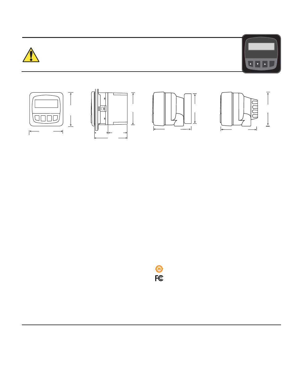
ProcessPro transmitters are available in two styles: panel mount and fi eld mount. The panel mount is supplied with the necessary
hardware to install the transmitter. This manual includes complete panel mounting instructions.
Field mounting requires one of two separate mounting kits. The 3-8051 Integral Mounting Kit joins the sensor and instrument together
into a single package. The 3-8050 Universal Mounting Kit enables the transmitter to be installed virtually anywhere.
Detailed instructions for integral mounting or other fi eld installation options are included with the 3-8051 Integral Mounting Kit or the
3-8050 Universal Mounting Kit (see Ordering Information).
Optional
Rear
Cover
102 mm
(4.0 in.)
96 mm
(3.8 in.)
106 mm
(4.18 in.)
82 mm
(3.23 in.)
92 mm
(3.6 in.)
97 mm
(3.8 in.)
56 mm
(2.2 in.)
41 mm
(1.6 in.
)
96 mm
(3.8 in.)
96 mm
(3.8 in.)
SIDE VIEW
Field Mount w/
8051 Integral kit
SIDE VIEW
Field Mount w/
8050 Universal base
Panel Mount
SIDE VIEW
FRONT VIEW
Field Mount &
Panel Mount
1. Specifi cations
Dimensions
3-8550.090-3 Rev. M 09/12 English
*3-8550.090-3*
English
4. Menu Functions
5. Troubleshooting
6. Ordering Information
Declaration of Conformity according to FCC Part 15
This device complies with Part 15 of the FCC rules.
Operation is subject to the following two conditions:
(1) This device may not cause harmful interference, and,
(2) This device must accept any interference received,
including interference that may cause undesired operation.