GF Signet 8900 Multi-Parameter Controller User Manual
Page 14
14
Signet 8900 Multi-Parameter
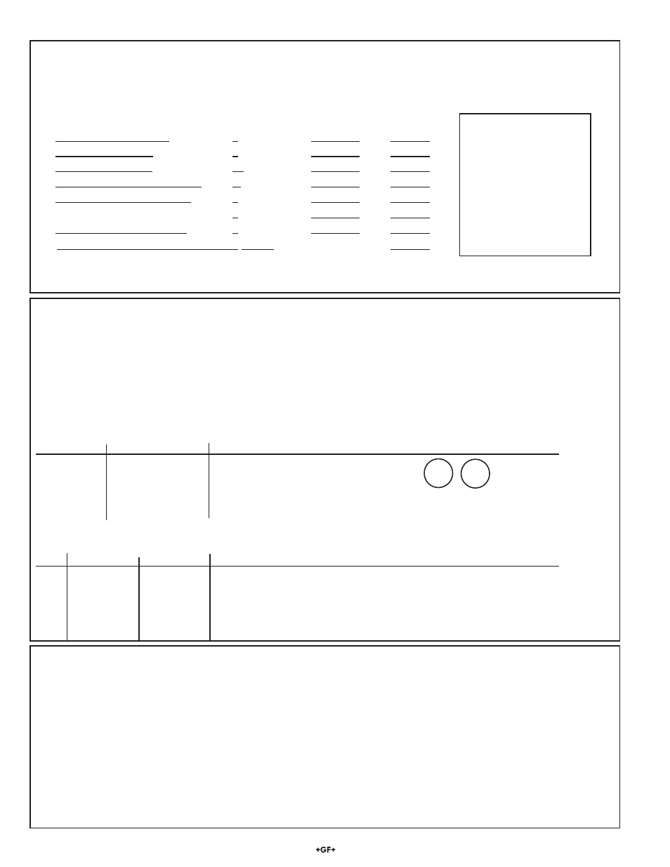
Step 1: Calculate the Total current requirements for digital (S
3
L) Branches
This information will determine the total current consumption of all digital (S
3
L) sensors on a branch of the digital (S
3
L) bus, as a
means of determining if the sensor load is within the current rating of the cable.
Fill in the chart to determine the current requirements for a specifi c set of sensors.
Maximum Current Consumption for Digital S
3
L Devices
Current
Quantity
Total
Example:
2350 Temperature Sensor
1 mA X
=
none
2450 Pressure Sensor
1 mA X
=
2 Press 1 mA x 2 = 2 mA
2551/2552 Magmeter*
15 mA X
=
2 Mags 15 mA x 2=30 mA
2750 pH/ORP Sensor Electronics
3 mA X
=
2 pH
3 mA x 2 = 6 mA
2850 Cond. Sensor Electronics
2 mA X
=
none
8058 Current-S3L Converter
3 mA X
=
none
8059 External Relay Module**
1 mA X
=
none
Total current requirement on digital (S
3
L) bus
mA
Total
38 mA
** The digital (S
3
L) communication link between the 8900 and the 8059 is powered by the 8900 and consumes 1 mA maximum.
However, the 8059 External Relay Module always requires a separate power source for its operation.
Step 2 Determine the Maximum length of each branch of the digital (S
3
L) Bus
This chart determines the maximum length of one branch of the digital (S
3
L) bus. This distance is important because it ensures that
the digital signal can successfully travel the length of the cable and still be detected by the 8900.
• Find the column nearest to the total current in this branch, as determined in step 1.
•
Find the cable gauge or wire dimensions that most accurately represent the cable being used.
•
The number at the intersection of these factors represents the maximum cable for one branch of the digital (S
3
L) bus.
•
The top section references AWG cables, the lower section is based on METRIC cables.
•
Dividing the sensors between two branches will greatly increase the maximum cable length of each branch.
Example: 40 mA total on one branch can sustain 70 ft of cable. 20 mA on two branches can sustain 140 ft on each branch.
Maximum Cable (AWG)
Power
Supply
Current
(mA)
AWG
Ω/ft
1
2
4
10
15
20
40
60
90
24
0.0277
1800 900 450 180 120 90 40 30 20
22
0.0175
2850
1420
710
280
190
140
70 40 30
20
0.0109
3000
2290
1140
450
300
220
110
70
50
18
0.0069
3000 3000 1810 720 480 360 180 120 80
16
0.0044
3000 3000 2840 1130 750 560 280 180 120
Maximum Cable (Metric)
Area Diameter
mm
2
mm
Ω/m
1 2 4 10 15 20 40 60 90
0.2 0.50463
0.0885
560 280 140 50 30 20 10 0 0
0.25
0.56419
0.0708
700 350 170 70 40 30 10 10 0
0.5 0.79789
0.0354
900 700 350 140 90 70 30 20 10
0.75 0.97721
0.0236
900 900 520 210 140 100 50 30 20
1 1.12839
0.0177
900 900 700 280 180 140 70 40 30
1.5 1.38199
0.0118
900 900 900 420 280 210 100 70 40
Feet
Meters
Step 3 Determine the Maximum total cable length of the digital (S
3
L)
Bus
The quality of the cable used in the bus determines the maximum length of all branches combined.
The maximum cable length may not exceed these limits, regardless of current requirements.
Cable
Capacitance
(pF/ft)
Max.
Total
Distance
Comments
<50 pF/ft
900 ft
Even the most economical cables meet this specifi cation.
<30 pF/ft
1500 ft
Cables from Signet fall into this category.
<15 pF/ft 3000
ft
Cables
meeting
this
specifi cation are very expensive network cables.
pF/m
Max.
Total
Distance
<150 pF/m
300 m
Even the most economical cables meet this specifi cation.
<100 pF/m
450 m
Cables from Signet fall into this category.
<50 pF/m
900 m
Cables meeting this specifi cation are very expensive network cables.
6.2.1
Digital Cable Length Calculations