Mounting the base unit, Blk red shld blk red s l shld blk s l shld, Relay 1 relay 2 enter – GF Signet 8900 Multi-Parameter Controller User Manual
Page 10: Din standard
10
Signet 8900 Multi-Parameter
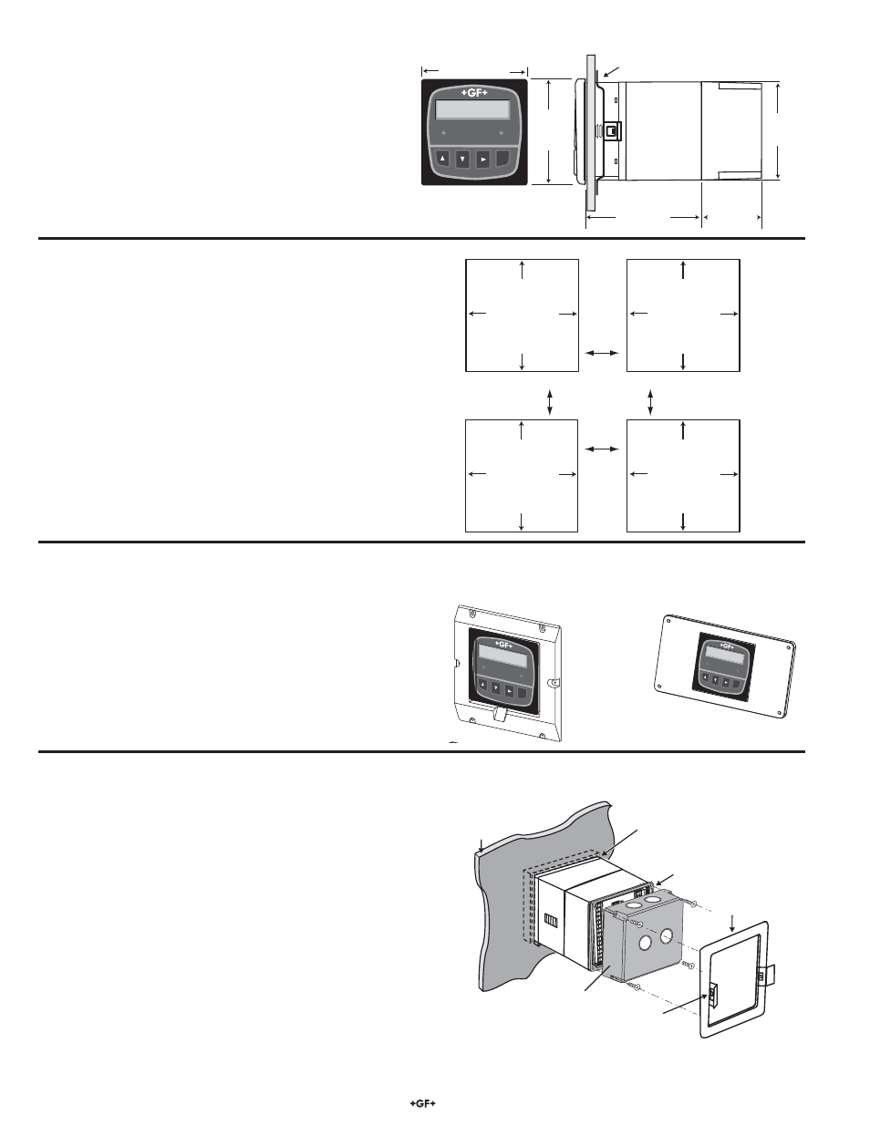
5. Mounting the Base Unit
The 8900 may be mounted in a panel, on a wall, or on virtually
any surface including shelves, racks and pipes. All methods of
mounting the 8900 make use of the Signet Quick-clip for holding
the instrument securely in place. This unique clip eliminates the
hassle of locating and drilling holes for mounting screws.
If the 8900 will be mounted in a panel, plug-in modules may be
installed either before or after the base unit is mounted. If an
accessory Wall Mount Bracket will be used, fi rst install plug-in
modules.
5.1 Panel Mounting
•
The 8900 enclosure conforms to the ¼-DIN standard, which
requires a panel opening of 92 mm x 92 mm (3.6 in. x 3.6 in.).
•
¼-DIN punches are available and recommended for creating
clean, precise openings quickly and easily in most instrument
panels.
•
Alternatively, a jigsaw or other cutting tool may be used.
An adhesive template is provided to help guide the cutting
process.
•
Recommended minimum clearance on all sides between
instruments and panel edges is 25 mm (1 in.) as illustrated.
•
Use an appropriate fi le as necessary to shape and size the
opening, and to remove burrs.
123 mm/
4.85 in.
56 mm/
2.21 in.
Splashproof
Rear Cover
(accessory)
96 mm/3.78 in.
96 mm/
3.78 in.
92 mm/
3.62 in.
Quick-clip
mounting
bracket
Multi-Parameter
Controller
C1 2.50 µS/cm
F2 58.43 GPM
Relay 1
Relay 2
ENTER
Multi-Parameter
Contro
ller
Relay 1
Relay 2
ENTER
C1 23.45 µS/cm
L2 -16.58 ft
Quick-clip
gasket on
front side
of panel
3-8050.395
Splashproof
rear cover
panel
terminals
mounting
bracket
O
U
T
2 O
U
T
1
P
O
W
E
R
C
O
M
M
P
O
R
T
/
O
U
T
4
O
U
T
3
R
E
LA
Y
2
R
E
L
A
Y
1
R
E
L
A
Y
4 R
E
L
A
Y
3
S
E
N
S
O
R
IN
P
U
T
S
C
NO
NC
NO
NC
C
C
NO
NC
NO
NC
C
+
-
+
-
N
L
+
-
BLK
RED
SHLD
BLK
RED
S L
SHLD
BLK
S L
SHLD
+
-
+
-
3
3
AC ONL
Y
Panel Cutout
92 x 92 mm
(+ 0.8, - 0 mm)
3.6 x 3.6 in.
(+0.031, -0 in.)
Panel Cutout
92 x 92 mm
(+ 0.8, - 0 mm)
3.6 x 3.6 in.
(+0.031, -0 in.)
Panel Cutout
92 x 92 mm
(+ 0.8, - 0 mm)
3.6 x 3.6 in.
(+0.031, -0 in.)
Panel Cutout
92 x 92 mm
(+ 0.8, - 0 mm)
3.6 x 3.6 in.
(+0.031, -0 in.)
minimum
clearance
25 mm
(1 in.)
To install 8900 in a panel:
1. Slide the 8900 into the opening from the front of the panel.
Ensure the Front Face Panel Gasket is properly seated
against the panel and around the instrument case.
2. Slide the Quick-clip mounting bracket over the back of the
instrument as illustrated. The Quick-clips will snap into
engagement with the molded latches on the side of the
instrument. Press the bracket against the inside of the panel
to secure the instrument fi rmly in place.
•
To remove, press the Quick-clips outward while pulling
the bracket away from the instrument panel. DO NOT
ALLOW THE INSTRUMENT TO FALL FORWARD OUT
OF THE PANEL OPENING! It may be necessary/helpful to
temporarily secure the instrument from the front with tape,
etc.
3-5000.399 Panel adapter,
5 in. x 5 in. to ¼-DIN
3-8050.392 Panel adapter,
½-DIN to ¼-DIN
Multi-Parameter
Controller
Relay 1
Relay 2
ENTER
C1 23.45 µS/c
m
L2 -16.58 ft
•
Two panel adapter accessories are available for installing the
8900 into panels with existing cutouts larger than the
1
/
4
DIN
standard.