Lr er al e r er m, Ac or dc power – GF Signet 8900 Multi-Parameter Controller User Manual
Page 18
18
Signet 8900 Multi-Parameter
l
r
er
al e
r
er
M
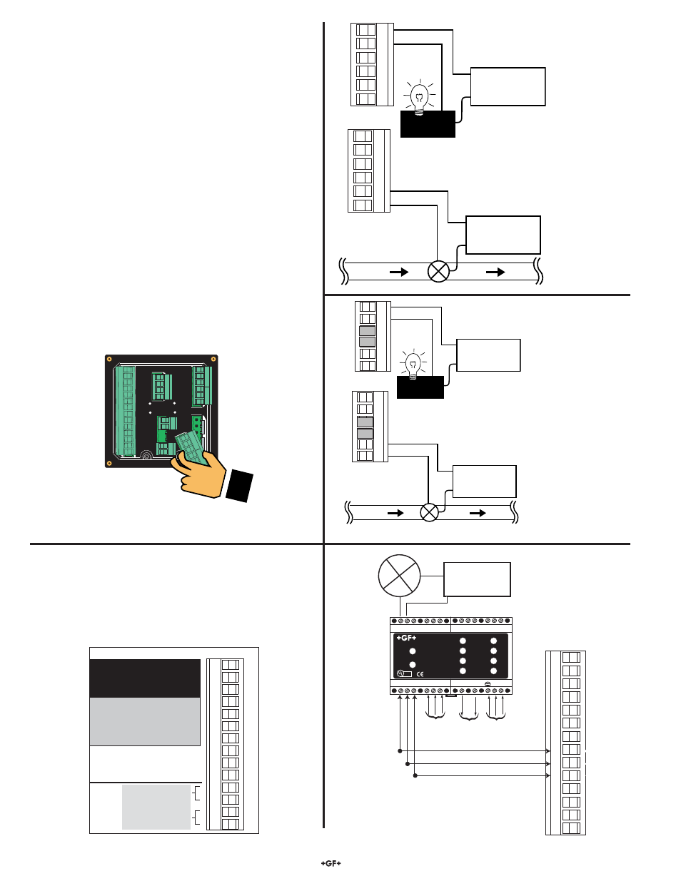
6.5 Relay Module (3-8900.403-X)
6.6 8059 External Relay Module
•
8059 external relay modules provide 4 additional
dry-contact relays.
•
External modules are controlled via the
digital (S
3
L) serial bus.
The alarm is OFF during normal
operation, and will go ON
according to 8900 Relay settings.
The valve is ON during normal
operation, and will go OFF
according to 8900 Relay settings.
RELAY A
RELAY B
+
S3L
-
+
S3L
-
OUTPUT 24VDC
+ -
AC INPUT
INPUT
PASS-THRU
L N
RELAY C
RELAY D
1
2
3
4
5
6
7
8
9
10
11
12
13
14
OUT
2 OUT
1
SENSOR INPUTS
8059-4AC
AC
Connect
S
3
L sensor
AC or DC
power
NC C NO
NC C NO
NC C NO
NC C NO
DC
COM
POWER
Signet 3-8059 Relay Module
Test A
Test B
Test C
Test D
Relay A
Relay B
Relay C
Relay D
LISTED
E171559
®
Solid State Relays (non-mechanical switches)
Normally open/closed operation:
Software
selectable
Max. pulse rate:
600 pulses per minute
(volumetric pulse & PWM modes)
400
pulses
per
minute
(prop.
pulse
mode)
Max. voltage rating:
30 VDC or 42 VAC p-p
Current rating:
50 mA DC or 50 mA AC RMS
On-state impedance:
30 ohms or less
Off-state leakage:
400 nA or less, AC or DC
Isolation:
Up to 48 VDC, or 48 VAC p-p
Transient protection:
Embedded, up to 48 V over-voltage
Dry-contact Relays (mechanical contacts)
Type:
SPDT
Form:
C
Max. pulse rate:
600 pulses per minute
(volumetric pulse & PWM modes)
400
pulses
per
minute
(prop.
pulse
mode)
Max. voltage rating:
30 VDC or 250 VAC
Current rating:
5 A
RELA
2 RELA
1
RELA
4 RELA
3
-
-
flow
AC or DC
power
valve
AC or DC
power
ALARM
-
-
Solid state relays have only two
terminals each. Normally open or
normally closed operation is software-
selectable in the RELAY menu.
ER
MM R
4 3
RE
RE
RE
4 RE
3
SESR S
3
3
-
-
1
2
3
4
5
6
8
9
10
11
12
13
14
-
3-8900.621C
I/O Module 3-8900.401-X
1
2
3
4
5
6
7
8
9
10
11
12
13
14
+5VDC (Black)
Freq. Input (Red)
GND (Shield)
+5VDC (Black)
Freq. Input 2 (Red)
S L (Red)
GND (White/Shield)
+5VDC (Black)
S L (Red)
GND (White/Shield)
3
3
Analog Output 1
Analog Output 2
(if applicable)
(if applicable)
Frequency
Input
1
Frequency
Input 2
OR
S3L
Input
2
S3L
Input
1
+
-
+
-