GF Signet 8860 Dual Channel Conductivity-Resistivity Controller User Manual
Caution, Installation, Specifi cations
CAUTION!
• Remove power to unit before wiring input and output connections.
• Follow instructions carefully to avoid personal injury.
• This product should only be used for the purposes and in the manner described in this manual.
Signet 8860 Dual Channel Conductivity/Resistivity Controller
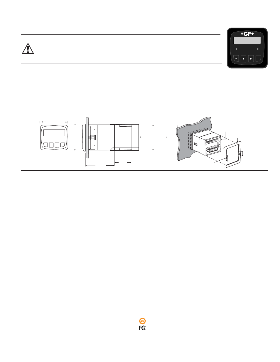
Installation
1. Punch out panel and de-burr edges. Recommended clearance on all sides between instruments is 1 inch.
2. Place gasket on instrument, and install in panel.
3. Slide mounting bracket over back of instrument until quick-clips snap into latches on side of instrument.
4. Connect wires to terminals.
5. To remove, secure instrument temporarily with tape from front or grip from rear of instrument. DO NOT RELEASE. Press
quick-clips outward and remove.
6. If cleaning is necessary, wipe the front of the unit with a damp cloth.
7. The live contacts on the back of this unit must be covered to avoid accidental shock hazard.
Specifi cations
General
Compatible electrodes:
Signet 2818 to 2823 (Standard or
Certifi ed Cond/Resist Sensors)
Enclosure:
• Rating: NEMA 4X/IP65 front (NEMA 4X Rear cover available)
• Case: PBT
• Panel case gasket: Neoprene
• Window: Polyurethane-coated polycarbonate
• Keypad: Sealed 4-key silicone rubber
• Weight: 8860-AC: 0.58 kg (1.28 lb) 8860: 0.55 kg (1.2 lb)
Display (Alphanumeric 2 x 16 LCD) :
• Contrast: User selected, 5 levels
• Update rate: 1.5 s
Sensor input range:
• Conductivity: 0.01 μS/cm to 400 000 μS/cm
• Resistivity: 10 k
•cm to 100 M•cm
• TDS: 0.023 to 200 000 PPM nominal (adjustable μS/PPM)
• Temperature:
-25 °C to 120 °C (-13 °F to 248 °F) PT 1000; 25 ºC = 1096
Accuracy:
• Conductivity/Resistivity: ± 2% of reading
• Temperature:
± 0.5 ºC (0 ºC to 100 ºC)
Electrical
Power requirements:
3-8860-AC: 100 to 240 VAC ± 10% , 50 to 60 Hz, 20VA or
11 to 24 VDC ±10%, regulated, 0.5 A max
3-8860:
11 to 24 VDC ±10%, regulated, 0.5 A max
Three 4 to 20 mA Outputs:
• Passive, isolated, fully adjustable and reversible
4 to 20 mA outputs are independently source selectable
• Max loop impedance:
150
@ 12 V, 450 @ 18 V, 750 @ 24 V
• Update rate: ~100 mS
• Accuracy: ±0.03 mA @ 25°C, 24 VDC
Open-collector outputs (2 available, optically isolated):
• 50 mA sink or source, 30 VDC max. pull-up voltage
• Programmable
for:
• High or Low setpoint with adjustable hysteresis
• Pulse operation (max. rate: 400 pulses/min)
• USP
standards
• Time delay: 0 s to 6400 s.
Relay outputs (up to 4 SPDT relays available)
• Maximum resistive load: 5 A @ 250 VAC, 5 A @ 30 VDC
• Isolation between open contacts: 500 V minimum
• Programmable
for:
• High or Low setpoint with adjustable hysteresis
• Pulse operation (max. rate: 400 pulses/min)
• USP
standards
• Time delay: 0 s to 6400 s
Environmental
•
Ambient operating temperature: -10 °C to 55 °C (14 °F to 131 °F)
• Storage
temperature:
-15 °C to 80 °C (5 °F to 176 °F)
• Relative humidity:
0 to 95%, non-condensing
• Maximum altitude:
2000 m (6562 ft)
• Insulation
category:
II
• Pollution
degree:
2
Standards and Approvals
CE
• EN61326: Immunity & Emissions for Control Equipment
• EN61010:
Safety
UL listed
Manufactured under ISO 9001 for Quality, ISO 14001 for
Environmental Management and OHSAS 18001 for Occupational
Health and Safety.
China RoHS (Go to www.gfsignet.com for details)
Declaration of Conformity according to FCC Part 15
This device complies with Part 15 of the FCC rules. Operation is
subject to the following two conditions:
(1) This device may not cause harmful interference, and, (2)
This device must accept any interference received, including
interference that may cause undesired operation.
Signet
Conductivity/Resistivity
Transmitter
C1 23.45 µS
C2 8.72 µS
Relay 1
Relay 2
ENTER
102 mm
(4.0 in.)
56 mm
(2.2 in.)
Panel Cutout
92 x 92 mm
(+ 0.8, - 0 mm)
3.6 x 3.6 in.
(+0.031, -0 in.)
Optional
Rear Cover
quick-clip
gasket on
front side
of panel
panel
terminals
mounting
bracket
RELA
Y 1
RELA
Y 2
RELA
Y 3
RELA
Y 4
N/C
N/O
COM
N/C
N/O
COM
N/C
N/O
COM
N/C
N/O
COM
RELA
Y 3,4
OPEN
C
O
LL 3,4
- OPEN COLL
4
-
OPEN COLL
3
SHLD
ISO GND
TE
MP 1
SGNL 1
SHLD
ISO GND
TEMP 2
SGNL 2
POWER
OUTPUT
OPTION
L
N
96mm (3.8 in.)
96 mm
(3.8 in.)
3-8860.090
Rev. G 11/12 English
*3-8860.090*
English