Appendix e: cloning using digital (s, L) (serial cloning) – GF Signet 8900 Multi-Parameter Controller User Manual
Page 45
45
Signet 8900 Multi-Parameter
Appendix E: Cloning using Digital (S
3
L)
(Serial
Cloning)
Cloning enables copying the programming from one unit into
another unit. After one 8900 is completely programmed, it
becomes a Master (SEND) unit that can download its settings to a
Slave (RECEIVE) 8900.
Are You Sure?
Press
All Settings
Will be Changed!
Clone
Instrument: >
Step 1: Controller Designations
1. Designate the 8900 controller that will receive the data and
refer to this controller as the Receiving Controller.
2. Designate the other 8900 controller as the Transmitting
Controller.
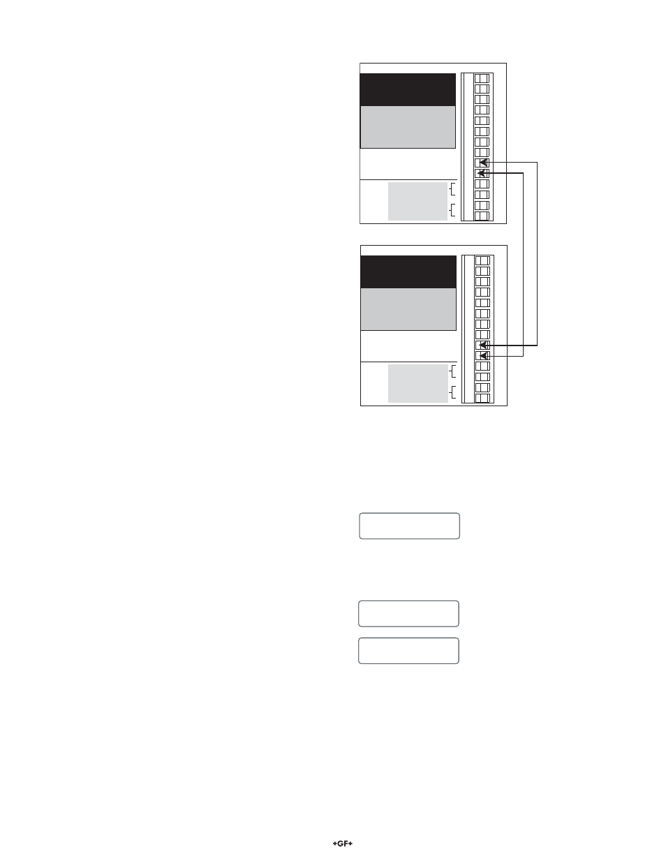
Step 2: Wiring
1. Connect terminal 9 of both controllers together with a single
wire conductor.
2. Connect terminal 10 of both controllers together with a single
wire conductor. See Figure 1.
Step 3: Confi gure the Receiving Controller
1. Go to the Option menu and scroll until you see the
“Clone Port” menu item and set the selection to “S3L”, if
not already set.
2. Scroll down to the “Clone Operation” menu item and set
it to “Receive”, if not already set.
3. Scroll down in the Option’s menu until you see the menu
item
"Clone Instrument".
4. Press the right arrow key to toggle the selection choices.
5. Press the ENTER key, when the “Yes” selection is
fl ashing, to proceed.
6. The message "All Settings Will be Changed" will be
displayed for about 3 seconds.
7. The message "Are You Sure?" will be followed by the
previous message and will also be displayed for about 3
seconds.
DO NOT press the ENTER key yet.
8. The Receiving Controller is now ready to start the cloning
process, but the Transmitting Controller must also be
confi gured to start the cloning process. Proceed to Step 4.
3-8900.621C
I/O Module 3-8900.401-X
1
2
3
4
5
6
7
8
9
10
11
12
13
14
+5VDC (Black)
Freq. Input (Red)
GND (Shield)
+5VDC (Black)
Freq. Input 2 (Red)
S L (Red)
GND (White/Shield)
+5VDC (Black)
S L (Red)
GND (White/Shield)
3
3
Analog Output 1
Analog Output 2
(if applicable)
(if applicable)
Frequency
Input
1
Frequency
Input 2
OR
S3L
Input
2
S3L
Input
1
+
-
+
-
Figure 1
Transmitting Controller
Receiving Controller