Positioner 1067, Appendix – Burkert Type 1067 User Manual
Page 99
POSITIONER 1067
E-47-
APPENDIX
A4 :
OPTION BOARD "BINARY POSITION INDICATION/BOOSTER"
(IDENT. 192801): MOUNTING AND CONNECTION
- The positioner must be equipped with the software version F, or higher. Check it in the
main menu, option END: it is displayed at the right-hand side of the screen.
- For positioners manufactured before 1996 mounting is only possible if the
motherboard is fitted with black connection blocks (if not, please contact you nearest
Bürkert
agent).
Technical characteristics
Positioner
Relay
- Operating voltage
: 24 VDC
- Contact type : closed
- Electric power consumption
: max. 30 W
- Commutation current : 0,5 A
- Electric connection
: screw terminals,
- Breaking capacity : 10 W
1,5 mm2 cross-
- Contact resistance : 100 mOhm
section
Mounting
- Disconnect the positioner from the voltage supply
- Unscrew the 4 screws of the positioner cover and open the cover
- Remove the 2 red jumpers from the motherboard
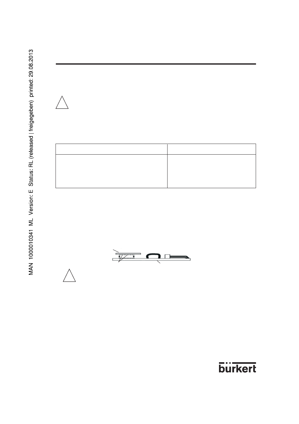
- Insert the optional board onto the motherboard (see figure below)
Make sure the pins correctly slide into the motherboard.
- Pass the cables through one of the 2 PG9 cable glands and dismantle them over 6 mm.
!
!
Option board
Motherboard
pins