Positioner 1067, 3 installation – Burkert Type 1067 User Manual
Page 63
POSITIONER 1067
E-11-
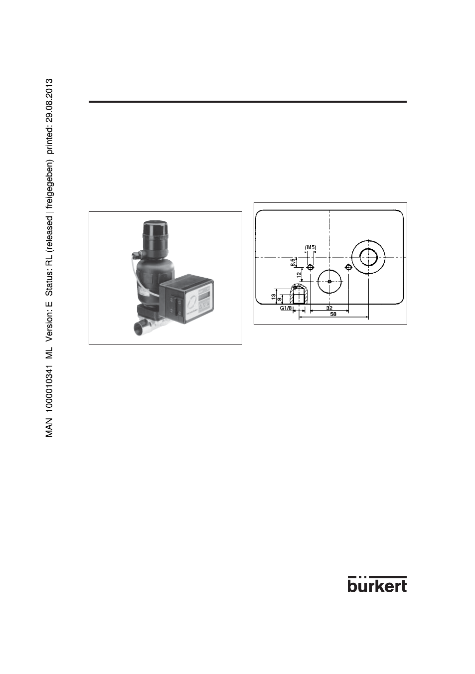
Fig. 11 Fitting to a 2731 continuous valve
with piston drive
Fig. 12 Rear view of positioner (variant 2)
Assembly
Assembly of variant 2 of the positioner to a continuous valve with piston drive.
A set of add-on parts (NAMUR adapter, Fig. 13) is provided for assembling variant 2 of the positioner
to a piston valve (e.g. 2731). It consists of a mounting plate "
1", two hollow bolts "2", three O-rings "3"
and two cheese-head bolts M5 "
4".
To assemble the positioner on a continuous valve with piston drive, the following steps should be
carried out (Fig. 13):
Place an O-ring "
3" in the recess of the mounting plate "1" (drive side). In the case of a large version,
place a second O-ring on the other side of the mounting plate.
Put two cheese-head bolts M5 "
4 "from the drive side through the 5-mm drillings in the mounting plate.
Screw the preassembled mounting plate "
1" to the two connection pieces of the valve drive with two
hollow bolts "
2" so that the lower connection piece is sealed by the O-ring.
Place an O-ring "
3" in the groove on the reverse side of the positioner.
Add the positioner to the mounting plate and screw it on with the two cheese-head bolts "
4".
3 INSTALLATION
3.1.2 Fitting the positioner variant 2 to a continuous valve with piston drive
Arrangement
A continuous valve with piston drive can be used with variant 2 of the positioner with the external path-
measuring system (Fig. 14). The positioner is placed on the valve and screwed to it (Figs. 11 and 12).
The valve position is transmitted directly via the spring-mounted rod of the path-measuring system (the
linear potentiometer).