Positioner 1067, 3 installation – Burkert Type 1067 User Manual
Page 65
POSITIONER 1067
E-13-
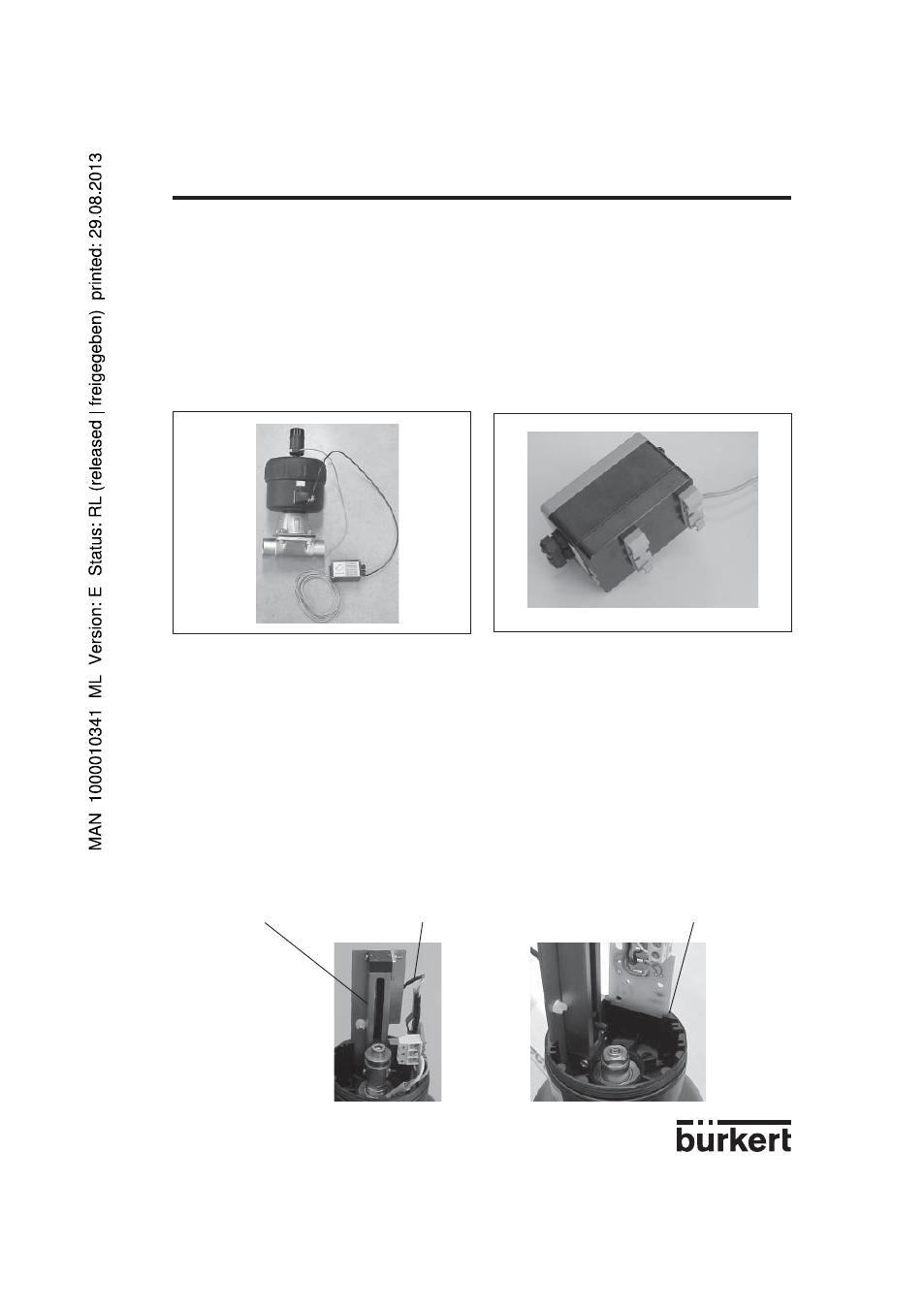
Fig. 15 Continuous valve with piston drive
and remote positioner (variant 3)
Fig. 16 Rear view of positioner for mounting
on a DIN rail
Assembly
Variant 3 of the positioner is mounted on a DIN rail.
To mount the external feedback/positional transducer, do the following (refer to Fig. 17):
a) Make sure that an O-ring has been inserted into the valve actuator (top). Insert ring "
6" if necessary.
b) Unscrew fastening screw "
3".
c) Place the plastic ring "
4" on the top of the actuator "5" (sizes 100 and 125 only) then screw the
external feedback/positional transducer (fig. 14) on it.
d) Tighten fastening screw "
3".
e) Unscrew housing "
11" of the external feedback/positional transducer.
f) The cable of the path-measuring system must be placed behind the latter so that it does not hinder
the displacement of the spindel of the feedback/positional transducer.
3.1.3 Fitting the positioner variant 3 for a continuous valve with piston drive
Arrangement
A continuous valve with piston drive can be used with variant 2 of the positioner with the external
feedback/positional transducer (Fig. 14) which is set on the valve and screwed to it (Fig. 15). The valve
position is transmitted directly via the spring-mounted rod of the path-measuring system (the linear
potentiometer).
Path-measuring system
Cable
Slot for the electronic board
3 INSTALLATION