Positioner 1067, 3 installation – Burkert Type 1067 User Manual
Page 66
E-14-
POSITIONER 1067
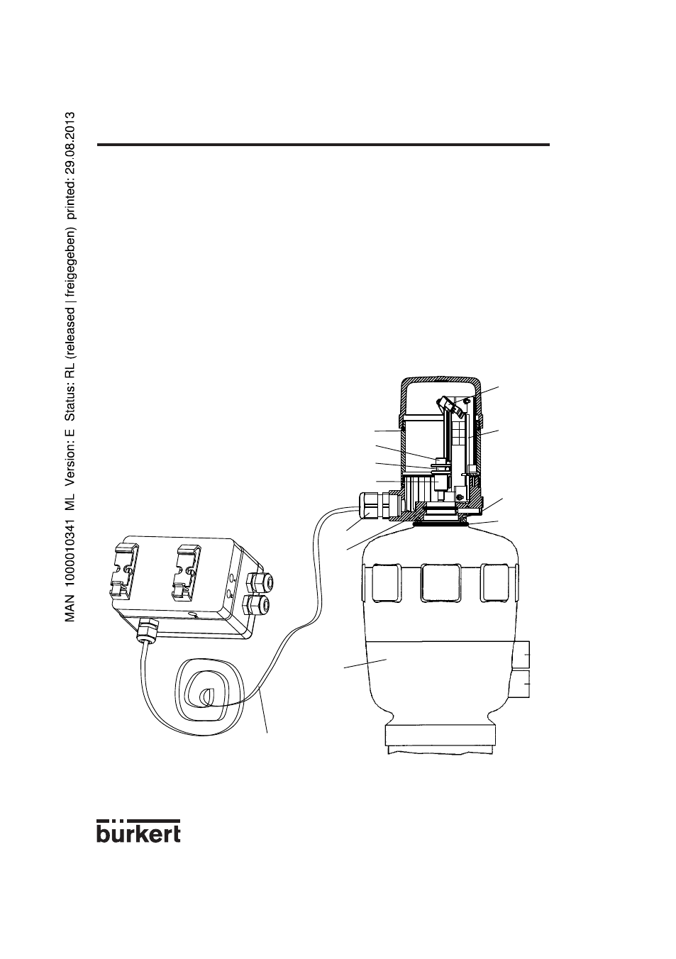
g) Place the cursor of the path-measuring system into the groove "
9" of the spindle "8" of the feed-
back/positional transducer and set this spindle onto the spindel of the actuator. Fasten screw "
10".
h) Insert electronic board "
2" into the slot of the positioner housing.
i) Inside the housing, connect plug "
1" of the path-measuring system to the connector of the electro-
nic board, with respect to the wire colours (blue mark)
j) Cut cable "
12" at the desired length and pull it through the cable gland "7" of the external feedback/
positional transducer.
k) Connect cable "
12" to the connector of the electronic board:
-
:
brown
A
:
white
+
:
green
l) Tighten the cable gland "
7".
m) Screw the housing "
11" of the external feedback/positional transducer.
+
-
A
1
2
4
5
6
7
8
12
3
9
10
11
Fig. 17 Diagram for the assembly of positioner variant 3 and external feedback/positional
transducer
3 INSTALLATION
- Type 1062 (112 pages)
- Type 8750 (64 pages)
- Type 8750 (82 pages)
- Type 1050 (4 pages)
- Type 8681 (40 pages)
- Type 8681 (90 pages)
- Type 8798 (2 pages)
- Type 8791 (4 pages)
- Type 8798 (106 pages)
- Type 8792 (136 pages)
- Type 8792 (252 pages)
- Type 8718 (34 pages)
- Type 8792 (118 pages)
- Type 8791 (15 pages)
- Type 8791 (106 pages)
- Type 8791 (184 pages)
- Type 8791 (28 pages)
- Type 8791 (21 pages)
- Type 8791 (154 pages)
- Type 0911 (76 pages)
- Type 0911 (46 pages)
- Type 0911 (64 pages)
- Type 0911 (84 pages)
- Type 1058 (31 pages)
- Type 1060 (4 pages)
- Type 1066 (112 pages)
- Type 1077-2 (33 pages)
- Type 1094 (12 pages)
- Type 1094 (41 pages)
- Type 1094 (82 pages)
- Type 1094 (126 pages)
- Type 1115 (25 pages)
- Type 1150 (99 pages)
- Type 1541 (2 pages)
- Type 5142 (6 pages)
- Type 8619 (134 pages)
- Type 8619 (40 pages)
- Type 8620 (177 pages)
- Type 8622 (4 pages)
- Type 8623 (130 pages)
- Type 8623 (90 pages)
- Type 8625 (118 pages)
- Type 8624 (124 pages)
- Type 8718 (254 pages)