Calibration of the control cabinet model – Burkert Type 8611 User Manual
Page 69
69
FunctionsoftheConfigurationLevel
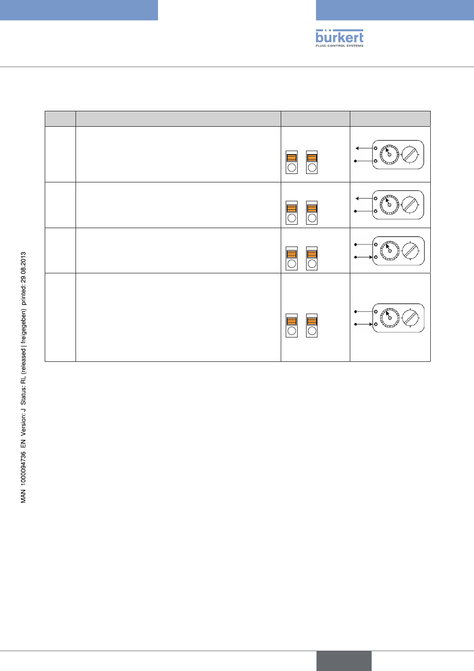
12.10. calibration of the control cabinet model
Menu
description
terminals
external circuit
SETA,
SETV
Use standard signal transmitter to apply a defined voltage
(max. 10 V) or defined current (max. 20 mA), as shown in
the columns on the right.
Use the arrow keys to change the displayed value until the
display corresponds to the default.
21
14
14 (+)
21 (–)
IN A,
IN V
Apply defined current to sensor input, as shown in the
columns on the right.
Use the arrow keys to change the displayed value until the
display corresponds to the default.
22
21
22 (+)
21 (–)
OUTA,
OUTV
Connect multimeter to terminals, as shown in the columns on
the right, and measure the current and voltage value.
Use the arrow keys to change the current or voltage value
until 20 mA or 10 V are displayed on the multimeter.
10
9
9
10
TEMP
Use standard signal transmitter to apply a temperature of
0 °C or a resistance of 100 Ω to the terminals, as shown in
the columns on the right. Press the up arrow key to accept
the value.
Increase temperature value to 100 °C or resistance to
138.506 Ω. Press the up arrow key to accept the value.
Confirm the
SAVE display with the ENTER key to save the
measurement.
20
19
19
20
Table 25:
Calibration of the control cabinet model
english
Type 8611