Burkert Type 8611 User Manual
Page 23
23
ElectricalInstallation
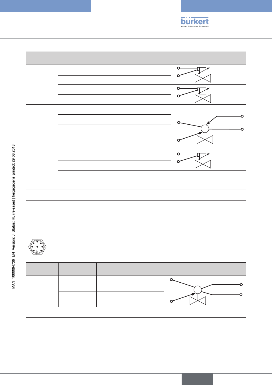
Output
signal:
pin
color
configuration
external circuit
3-point
(
MODE =
3P – T)
1 (
BO3) brown
(+) Valve 1
NC / NO valve
1
2
2
white
(–) Valve 1
3
blue
(–) Valve 2
NC / NO valve
3
4
4 (
BO4) black
(+) Valve 2
1)
4 - 20 mA
or 0 - 10 V
(
MODE =
4 – 20 /
0 – 10)
External
supply
1
brown
+ 24 V DC supply (max. 1A)
+ 24 V DC
M
2
4
GND
External supply
2
white
GND (4 - 20 mA or 0 - 10 V)
3
blue
GND supply
4
(
AOUT)
black
+ 4 - 20 mA or
0 - 10 V manipulated variable
2-point
(
MODE =
2P – T)
1 (
BO3) brown
(+) Valve 1
NC / NO valve
1
2
2
white
(–) Valve 1
3
blue
not connected
4
black
not connected
1) Only available for identification number 182383
Table 7:
Configuration of circular plug-in connector M8, 4-pole
circular plug-in connector M12, 8-pole
5
4
3
2
1
8
7
6
Output
signal:
pin
color
configuration
external circuit
2)
4 - 20 mA
or 0 - 10 V
(
MODE =
4 – 20 /
0 – 10)
4
(AOUT)
yellow
4 - 20 mA or
0 - 10 V manipulated variable
+ 24 V DC
M
4
6
GND (24 V)
6
pink
GND – Analog output
2) Available for all models except for identification number 182383
Table 8:
Configuration of circular plug-in connector M12, 8-pole
english
Type 8611