Burkert Type 8611 User Manual
Page 26
26
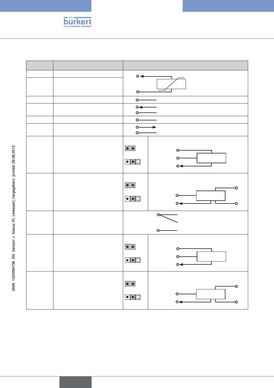
ElectricalInstallation
terminal block 3
terminal
configuration
external circuit
19
GND – Pt 100, RTD
(0 ... 200 °C)
19
20
Pt 100
20
(
AIN3)
(+) Pt 100, RTD (power supply)
21
GND – Analog input
21
A-GND
22
(
AIN1)
(+) Process value input
4 - 20 mA / 0 - 10 V
22
21
4 - 20 mA / 0 - 10 V (source)
A-GND
23
GND – Sensor, actuating element
23
GND
24
24 V DC sensor supply or
actuating element
24
23
24 V DC - Out (max. 1 A)
GND
25
Supply of
Type 8611
(
DIN3)
Frequency input 2
(NPN or PNP)
Q
2
for ratio control
(
MODE = RATI)
Jumper 2
NPN
PNP
Transmitter
12 or 24
24 V DC
GND
11 or 23
Clock
25
Supply of 8611
25
External
supply
(
DIN3)
Frequency input 2
(NPN or PNP)
Q
2
for ratio control
(
MODE = RATI)
Jumper 2
NPN
PNP
Transmitter
GND
11 or 23
GND
Supply
Clock
25
External supply
26
(
DIN2)
(+) Binary input
26
1, 11, or 23
0 ... 2.7 V (log. 0)
3 ... 30 V (log. 1)
max. 1 kHz
GND
27
Supply of
Type 8611
(
DIN1)
Frequency input 1
(NPN or PNP)
Actual value flow-rate /
Q
1
for ratio control
(
MODE = RATI)
Jumper 1
NPN
PNP
Transmitter
12 or 24
24 V DC
GND
11 or 23
Clock
27
Supply of 8611
27
External
supply
(
DIN1)
Frequency input 1
(NPN or PNP)
Actual value flow-rate /
Q
1
for ratio control
(
MODE = RATI)
Jumper 1
NPN
PNP
Transmitter
GND
11 or 23
GND
Supply
Clock
27
External supply
Table 11:
Configuration of terminal block 3
english
Type 8611