Heat flow addendum, Programming – Dynasonics TFXP Series Transit Time Ultrasonic Flow Meter User Manual
Page 99
Rev. 5/09
-A.3-
TFXP
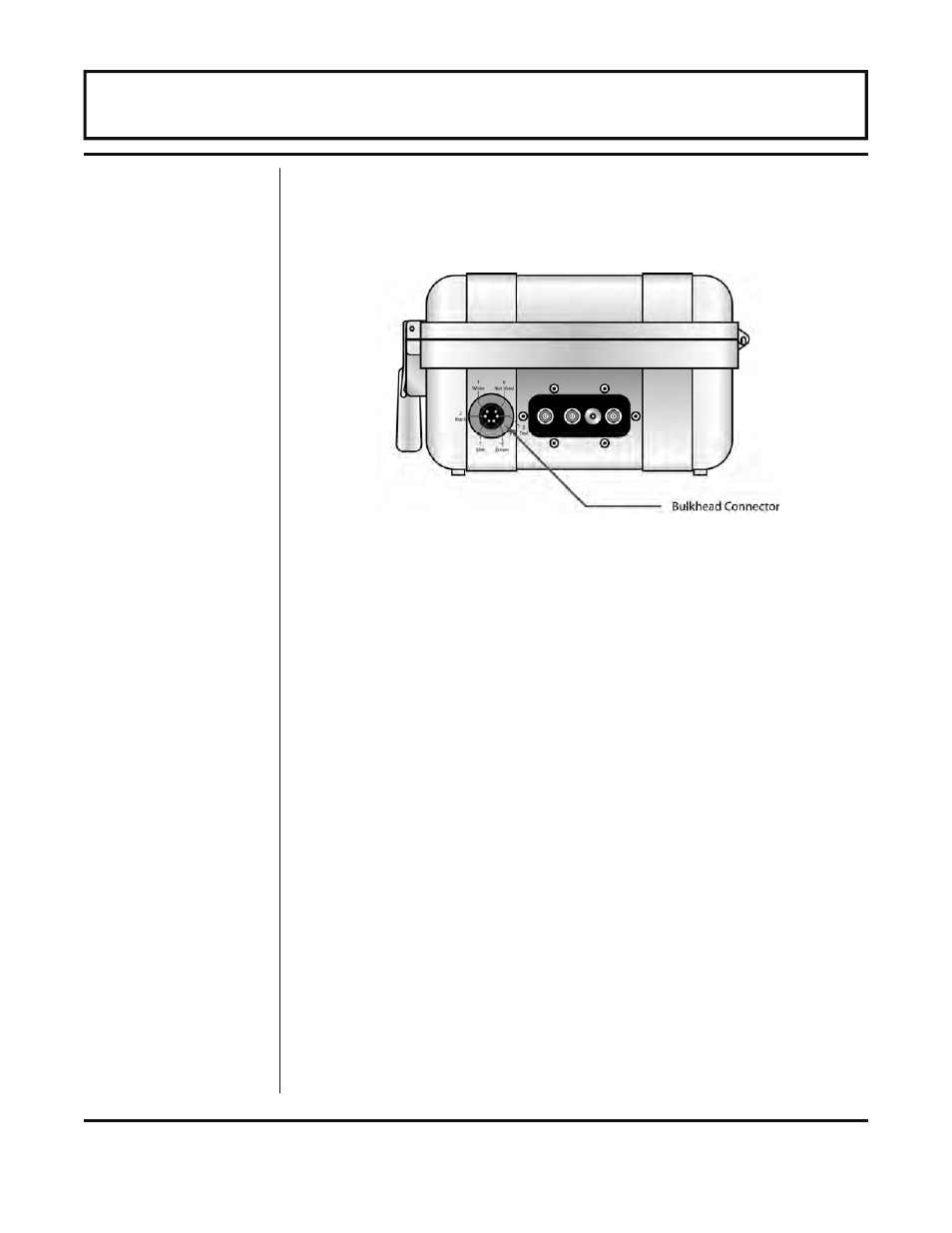
5. Route a cable from the electrical junction box back to the TFX
flow meter. Connect the RTDs as illustrated in Figure A.2.
Note
that the SNS1 and DRV1 wires originate from the same location
on the RTD.
Transmitter Programming
1. The RTDs included with the TFX heat flow option have been
factory calibrated and are marked with an identification as to
which terminal, #1 or #2, the RTD has been calibrated. If
recalibration of the RTDs is required or RTDs other than those
supplied with the TFX are being utilized, the ULTRALINK™
software utility will be required to enter calibration values.
ULTRALINK™ can also be used to configure all operating
parameters of the heat flow instrument.
2. To properly measure heat delivery, the specific heat capacity of
the liquid must be entered. When a liquid is chosen from the FL
TYPE list, a default specific heat will be loaded. This default
value is displayed as SP HEAT in the BASIC MENU. If the
actual specific heat of the liquid is known or if it differs from the
default value, press the ENTER key and modify the value.
Press the ENTER key to save the value. See the values listed
in Tables 1 and 2 for specific values. Enter a value that is the
mean of both pipes.
3. The RATE UNIT can be displayed as four different values; BTUs,
MBTU, MMBTU, or TON. Select the proper unit from the RATE
Figure A.2 — RTD Connection
Programming
HEAT FLOW ADDENDUM