Page 2, Dsp menu, Ser menu – Dynasonics TFXP Series Transit Time Ultrasonic Flow Meter User Manual
Page 105: Out2 men sen menu, Sec menu
CH PSWD?
0-9999
DSP MENU
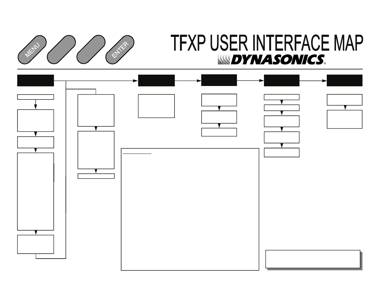
Keypad Operations
1. The (soft)MENU key is pressed from RUN mode to enter PROGRAM mode. The (soft)EXIT key is
pressed in PROGRAM mode to exit configuration parameters and menus. If changes to any
configuration parameters have been made, the user will be prompted with a SAVE? (soft)YES or (soft)
NO when returning to RUN mode. If no changes have been made, the user will not be prompted to
SAVE. The UP/DOWN ARROW keys are used to scroll through menus and configuration parameters.
The ARROW keys can also be used to adjust parameter numerical values. In RUN mode the UP/
DOWN ARROW keys are used to adjust the display contrast level.
2. The Numerical Keypad is used to entering numerical values.
3. The (soft)ACCEPT key is used to accept configuration parameter changes.
4. The (soft)SELECT key is used to
•
configure the engineering units on the graphics display ― Press the (soft)SELECT key from
RUN mode to highlight the engineering unit presently being displayed on the graphics display
(pressing the SELECT key multiple times will toggle the highlighted unit from line to line). Use
the UP/DOWN ARROW keys to select display units of
•
RATE
•
TOTAL (Net Only)
•
Sound Speed FPS
•
Sound Speed MPS
•
SIGNAL STRength
•
¹ TEMP 1
•
¹ TEMP 2
•
¹ TEMP DIFF
From the Display Menu, the number of graphics display lines can be toggled between two and
four lines.
•
access the configuration parameters in the various menus.
•
initiate changes in configuration parameters.
DISPLAY LINES
1. 2 Lines
2. 4 Lines
BACK LIGHT TIME
30 SEC
1 MIN
5 MIN
ALWAYS ON
TOT RES
NO
YES
SYS RSET
NO
YES
SER MENU
SIG C-OFF
SUB FLOW
COR FTR
0.500-1.500
OUT2 MEN
SEN MENU
XDUCER TYP
DTTN
DTTH
DTT 1500
DTTSnC
DTTSnP
OUT2
OPTIONS
RATE
FL 0H
FL
25KH
4-20MA
FL 4MA
FL
20MA
CAL
4MA
CAL
20MA
4-20
TST
RTD
RTD1
A
RTD1
B
RTD2
A
RTD2
B
Page 2
Date: 5/2009
Revision: none Revision Date: none
Software Version: 1.50.7080
V
V
RELAY
RELAY
1
NONE
TOTALIZE
TOT MULT
FLOW
ON
OFF
SIG
STR
ON
OFF
ERRORS
RELAY
2
NONE
TOTALIZE
TOT MULT
FLOW
ON
OFF
SIG
STR
ON
OFF
ERRORS
RS232
RS232
MO
HOST
UIF
RS232
BA
1200
2400
9600
19200
NONE
RS485
RS485
MO
SLAVE
MASTER
RS485
BA
1200
2400
9600
19200
ADDRESS
1-127
¹ Selection only visible when RTD output module is activated.
RTD
RTD1 A
RTD1
B
RTD2
A
RTD2
B
SET ZERO
NO
YES
D-FLT 0
NO
YES
SEC MENU