Part 4 - software utilities – Dynasonics TFXP Series Transit Time Ultrasonic Flow Meter User Manual
Page 80
Rev. 5/09
-4.2-
TFXP
Initialization
Connect the infrared communications adapter to a PC
communication port and point the communicator at the TFXP
infrared window located in the lower right-hand corner of the
keypad. If meter is ordered with either ISO-MOD RS232 or ISO-
MOD RS485 options, connect the PC communications cable directly
to the DB-9 connection located on the side of the TFXP meter.
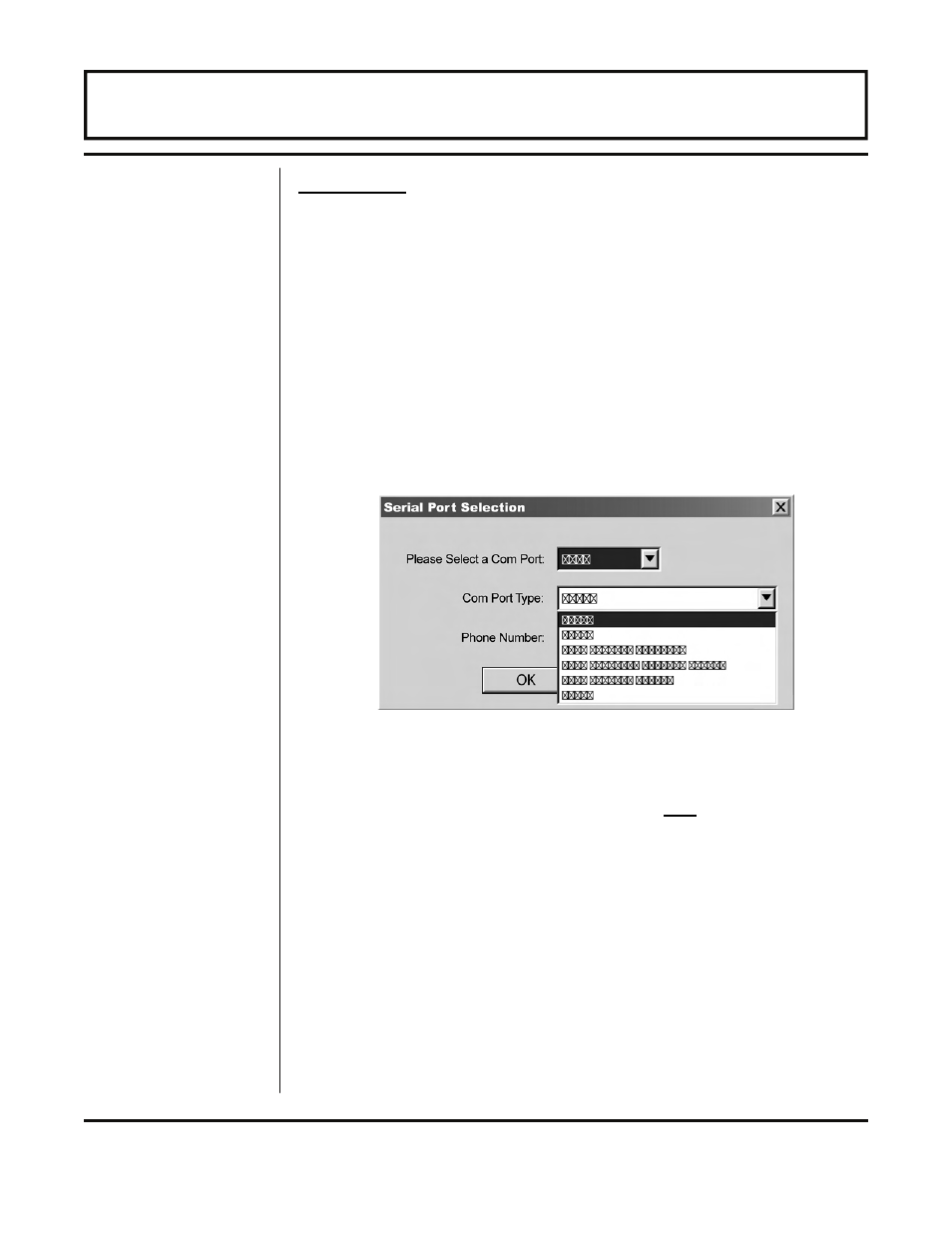
Click on the Communications button in the menu bar. Next click
on Initialize. Choose the appropriate COM port and interface type.
For the IR adapter choose IrDA Actisys IR220L. If either an
RS232C or RS485 communications module are used, select the
appropriate choice in the same drop down menu.
Successful communications between the TFX meter and computer
are indicated by a green “OK” in the COMM box in the lower right-
hand corner of the Data Display screen and the “Last Update
Time” near the bottom of the text area of the left-hand side is
tracking the time of the computer the TFX is connected to.
NOTE: For help in establishing communications with the TFX
meter, see “TFX Communications Using ULTRALINK™” in the
Appendix of this manual.
The first screen is the “Data Display” screen, see Figure 4.2 on
page 4.3, which contains real-time information regarding flow rate,
totalizer accumulation, system signal strength, diagnostic data and
the flow meter’s serial number. Click on the button labeled
Configuration for updating flow range, liquid, pipe and I/O
operating information.
Figure 1 — Serial Port Selection
PART 4 - SOFTWARE UTILITIES