Quick-start operating instructions, Connections – Dynasonics TFXP Series Transit Time Ultrasonic Flow Meter User Manual
Page 7
Rev. 5/09
-1.5-
TFXP
2. TRANSDUCER/POWER CONNECTIONS
A. Route the transducer cables from the transducer mounting
location back to the TFXP transmitter. If additional cable and
connections are required, ensure that they are RG59 75 Ohm
compatible.
NOTE: The transducer cable carries low level, high frequency
signals. In general, it is not recommended to add additional cable to
the cable supplied with the DTTN, DTTH or DTTS transducers. If
additional cable is required, contact the Dynasonics factory to
arrange an exchange for a transducer with the appropriate length of
cable. Cables to 990 feet (300 meters) are available. If additional
cable and connections are added, ensure that they are RG59
75 Ohm compatible.
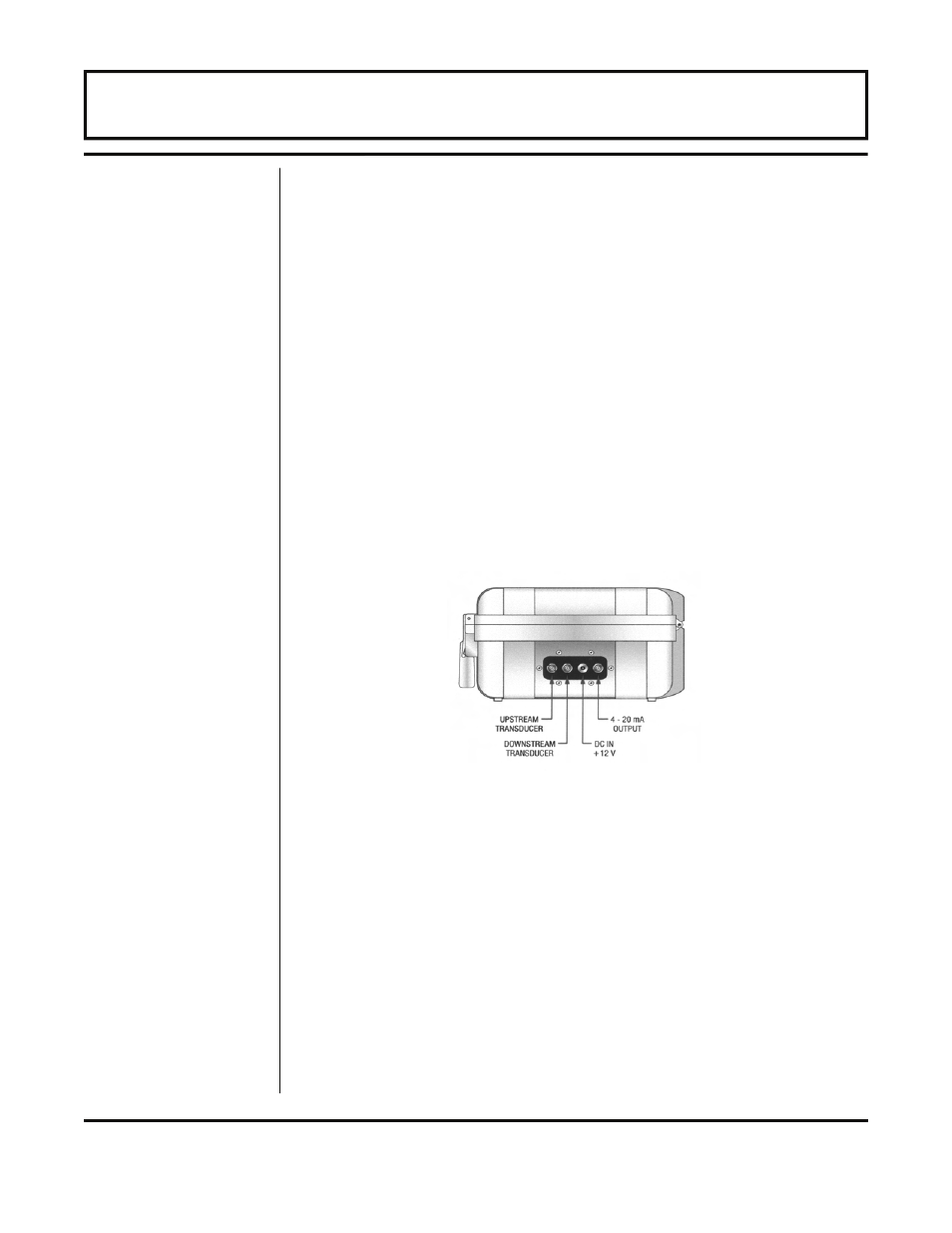
B. Refer to the wiring diagram located on the inside of the TFXP
transmitter and Figure 1.3 for proper power and transducer
connections.
3. PIPE PREPARATION AND TRANSDUCER MOUNTING
DTTN and DTTH Transducers
A. Place the flow meter in signal strength measuring mode.
This value is available on the TFXP display (Service Menu) or
in the Data display of the ULTRALINK™ software utility.
B. The piping surface, where the transducers are to be
mounted, must be clean and dry. Remove loose scale, rust
and paint to ensure satisfactory acoustical bonds. Grind
rough surfaces of pipes to smooth bare metal. Plastic pipes
do not require preparation other than cleaning.
Connections
QUICK-START OPERATING INSTRUCTIONS
Figure 1.3 — Transmitter Connections