Part 3 - keypad configuration, Transducer spacing, Engineering units rate – Dynasonics TFXP Series Transit Time Ultrasonic Flow Meter User Manual
Page 51
Rev. 5/09
-3.13-
TFXP
Transducer
Spacing
XDCR SPAC -- Transducer Spacing Calculation (Value)
1. ENGLSH
(Inches)
2. METRIC (Millimeters)
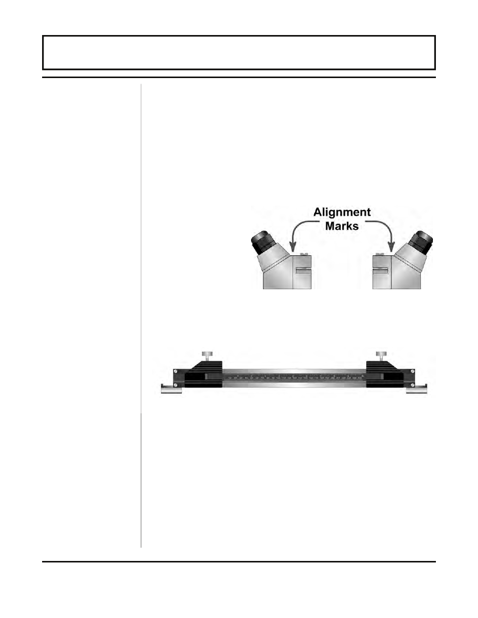
This value represents the one-dimensional linear measurement
between the transducers (the upstream/downstream measurement
that runs parallel to the pipe). This value is in inches if Englsh was
selected as Units; in millimeters if Metric was selected. This
measurement is taken between the alignment marks which are
scribed into the sides of the transducer blocks. See Figure 3.3.
If the transducers are being mounted using a transducer track
assembly, a measuring scale is etched into the track. Using the
alignment marks, place one transducer at 0 and the other at the
appropriate measurement.
RATE UNT -- Engineering Units for Flow Rate (Choice)
1. Gallons (GALLONS)
2. Liters
(LITERS)
3. Millions of Gallons (MGAL)
4. Cubic Feet
(CUBIC
FT)
5. Cubic Meters
(CUBIC ME)
6. Acre Feet
(ACRE
FT)
7. Oil Barrels
(OIL
BARR)
[42 Gallons]
Engineering
Units
RATE
Figure 3.3 —
Transducer
Alignment Marks
Figure 3.3 — Mounting Track Spacing
PART 3 - KEYPAD CONFIGURATION