Part 2 - transducer & rtd installation, Entering pipe and liquid data, Table 2.3 – Dynasonics TFXP Series Transit Time Ultrasonic Flow Meter User Manual
Page 24: Transducer mounting modes - dtts / dttc
Rev. 5/09
- 2.6 -
TFXP
The TFX system calculates proper transducer spacing by utilizing
piping and liquid information entered by the user. This information
can be entered via the keypad on a TFXP or via the optional
ULTRALINK™ software utility.
NOTE: Transducer spacing is calculated on “ideal” pipe. Ideal pipe
is almost never found so the transducer spacing distances should
be considered as starting points. An effective way to maximize
signal strength is to configure the display to show signal strength, fix
one transducer on the pipe and then starting at the calculated
spacing move the remaining transducer small distances forward and
back to find the maximum signal strength point.
Entering Pipe
and Liquid
Data
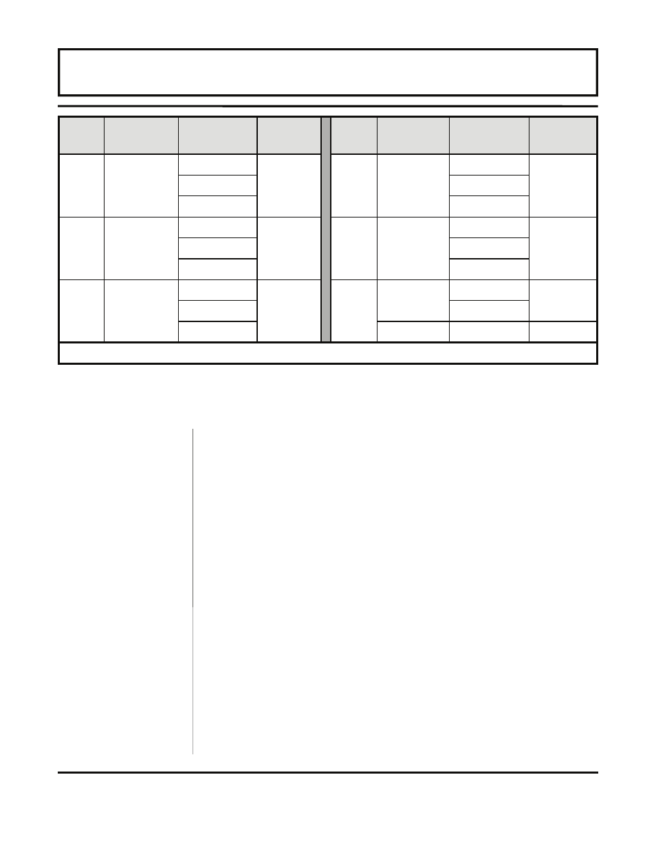
Table 2.3
—
Transducer Mounting Modes - DTTS / DTTC
Size Frequency Transducer
Mounting
Mode
Size Frequency Transducer
Mounting
Mode
1/2
2 MHz
DTTSnP
W
1-1/4 2
MHz
DTTSnP
W
DTTSnC DTTSnC
DTTSnT DTTSnT
3/4
2 MHz
DTTSnP
W
1-1/2
2 MHz
DTTSnP
W
DTTSnC DTTSnC
DTTSnT DTTSnT
1
2 MHz
DTTSnP
W
2
1 MHz
DTTSnP
V
DTTSnC DTTSnC
DTTSnT
2 MHz
DTTSnT
W
NOTE: DTTS transducer designation refers to both DTTS and DTTC transducer types.
PART 2 - TRANSDUCER & RTD INSTALLATION