Part 2 - transducer & rtd installation – Dynasonics TFXP Series Transit Time Ultrasonic Flow Meter User Manual
Page 32
Rev. 5/09
- 2.14 -
TFXP
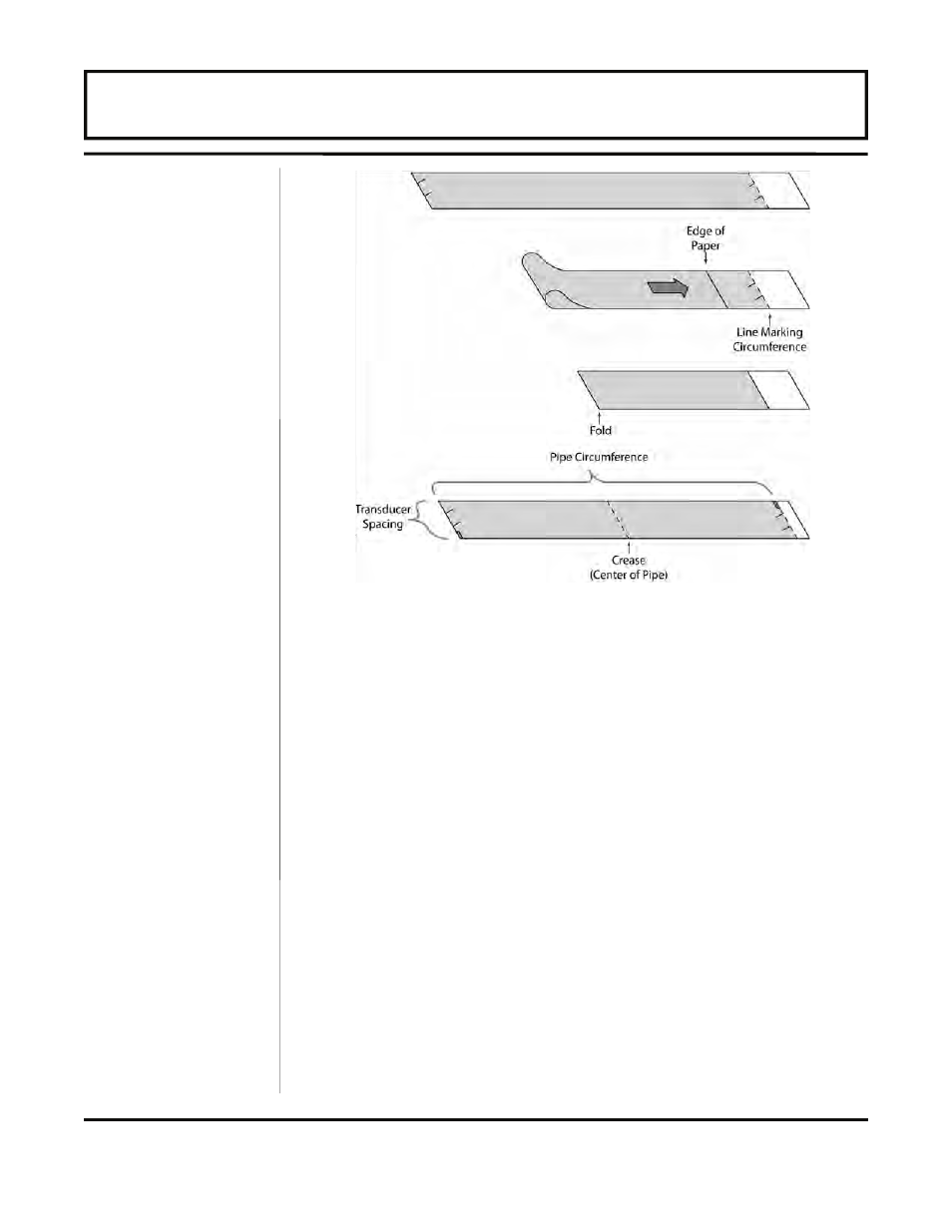
3. Crease the paper at the fold line. Mark the crease. Place a mark
on the pipe where one of the transducers will be located. See
Figure 2.2 on page 2.8 for acceptable radial orientations. Wrap
the template back around the pipe, placing the beginning of the
paper and one corner in the location of the mark. Move to the
other side of the pipe and mark the pipe at the ends of the
crease. Measure from the end of the crease (directly across the
pipe from the first transducer location) the dimension derived in
Step 2, Transducer Spacing. Mark this location on the pipe.
4. The two marks on the pipe are now properly aligned and
measured.
If access to the bottom of the pipe prohibits the wrapping of the
paper around the circumference, cut a piece of paper 1/2 the
circumference of the pipe and lay it over the top of the pipe.
1/2 Circumference = Pipe O.D. × 1.57
The transducer spacing is the same as found in the
Transducer Positioning section on page 2.10.
Mark opposite corners of the paper on the pipe. Apply
transducers to these two marks.
Figure 2.10 — Bisecting the Pipe Circumference
PART 2 - TRANSDUCER & RTD INSTALLATION