Heat flow addendum, Installation – Dynasonics TFXP Series Transit Time Ultrasonic Flow Meter User Manual
Page 98
Rev. 5/09
-A.2-
TFXP
Installation
Installation
1. Follow the instructions outlined in the standard TFX manual for
proper installation of the ultrasonic transducers. After
installation, verify that the signal strength is sufficient for stable
flow readings and, if possible, perform a Zero flow calibration on
the pipe. Please note that all readings require a full pipe of
liquid.
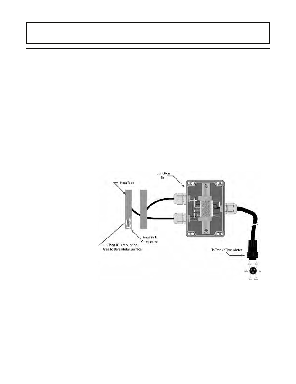
2. Select areas on the inlet and outlet pipes where the RTDs will
be mounted. Remove or peel back the insulation all the way
around the pipe in the installation area. Clean an area slightly
larger than the RTD down to bare metal on the pipe.
3. Place a small amount of heat sink compound on the pipe in the
RTD installation location. See Figure A.1 Press the RTD firmly
into the compound. Fasten the RTD to the pipe with the
included heater tape.
4. Route the RTD wires to an electrical junction box in close
proximity to the installation location. Secure the RTD wires
such that they will not be pulled on or abraded inadvertently.
Replace the insulation on the pipe.
Figure A.1 — Surface Mount RTD Installation
HEAT FLOW ADDENDUM