Part 1 - tfxp transmitter connections, Standard 4-20 ma output – Dynasonics TFXP Series Transit Time Ultrasonic Flow Meter User Manual
Page 16
Rev. 5/09
-1.14-
TFXP
The standard 4-20 mA output may be replaced with one of the
following five ISO-MODs: dual-relay, rate pulse, RS232C, RS485
and heat flow (RTD). TFXP supports one ISO-MOD input/output
module in addition to the optional data logger. All modules are field
configurable by utilizing the keyboard or ULTRALINK™ interface.
Field wiring connections to ISO-MODs are quick and easy using
pluggable terminals.
The 4-20 mA Output Module interfaces with virtually all recording
and logging systems by transmitting an analog current signal that is
proportional to system flow rate. Independent 4 mA and 20 mA
span settings are established in software using the FL4MA and
FL20MA settings in the OUTPUT2 configuration menu. These
entries can be set anywhere in the -40 to +40 fps (-12 to +12 mps)
measuring range of the instrument. Output resolution of the module
is 12-bits (4,096 discrete points). The module can drive up to 800
Ohms of load with its internally generated 24 volt power source.
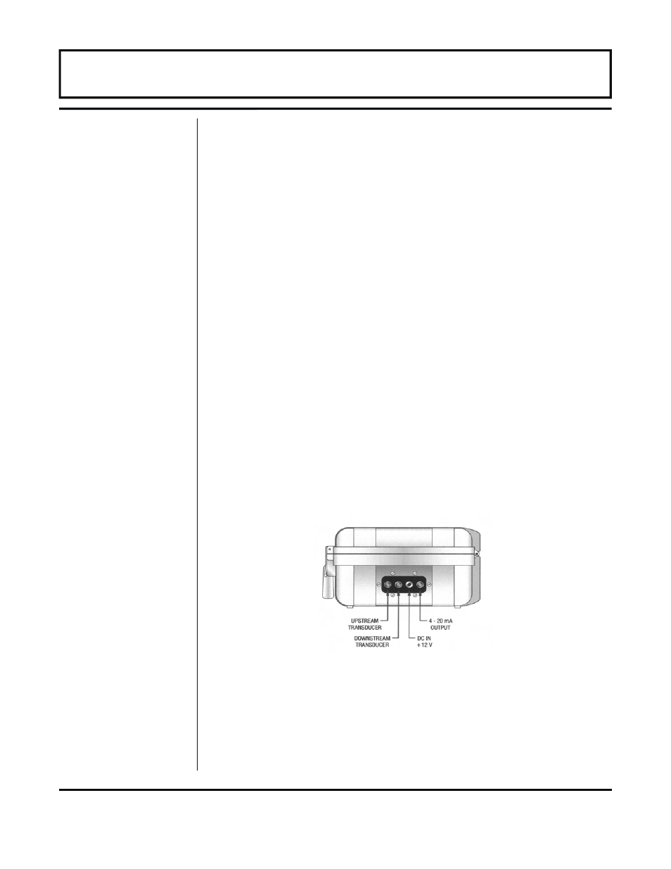
A 4-20 mA output interface cable has been included with the TFXP
package. Connect the 1/4-turn BNC connection to the jack located
on the side of the flow meter. See Figure 1.6. The red clip on the
cable provides the positive leg of the output and the black clip
provides the negative side. Verify that the sum of the resistances in
the loop does not exceed 800 Ohms. The TFXP output is configured
to source current.
Refer to Part 3 of this manual for detailed information regarding the
configuration, calibration and testing of the 4-20 mA output.
PART 1 - TFXP TRANSMITTER CONNECTIONS
Standard
4-20 mA
Output
Figure 1.6 — 4-20 mA Output Connections