Part 2 - transducer & rtd installation, Insertion rtd installation – Dynasonics TFXP Series Transit Time Ultrasonic Flow Meter User Manual
Page 37
Rev. 5/09
- 2.19 -
TFXP
Insertion RTD Installation
Insertion RTDs are typically installed through 1/4" compression
fittings and isolation ball valves.
1. It is recommended that insertion RTDs be mounted
downstream of the flow measurement transducers to avoid
causing flow instability in the flow measurement region.
2. Insert the RTD into the flow stream so that a minimum of
0.25" of the probe tip extends into the pipe. See Figure 2.14
on page 2.20.
3. RTDs should be mounted within ±45 degrees of the side of a
horizontal pipe. See Figure 2.15 on page 2.20. On vertical
pipes the orientation is not critical.
4. Route the RTD cables back to the TFX flow meter. If the
cables are not long enough to reach the TFX, route the
cables to an electrical junction box and add additional cable
from that point. Use 3-wire shielded cable, such as Belden
9939 or equal, for this purpose.
5. Secure the RTD cable so that it will not be pulled on or
inadvertently abraded.
Insertion RTD
Installation
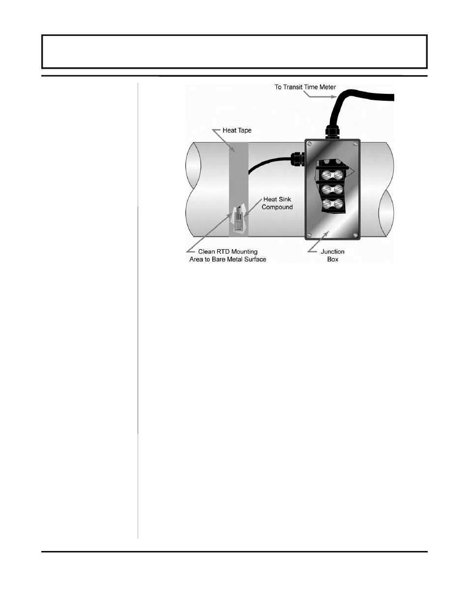
Figure 2.13 — Surface Mount RTD Installation
PART 2 - TRANSDUCER & RTD INSTALLATION