Part 2 - transducer & rtd installation, Z-mount transducer installation – Dynasonics TFXP Series Transit Time Ultrasonic Flow Meter User Manual
Page 31
Rev. 5/09
- 2.13 -
TFXP
2. On horizontal pipes, mount the transducer in an orientation so
that the cable exits at ±45° from the side of the pipe. Do not
mount with the cable exiting on either the top or bottom of the
pipe. On vertical pipes the orientation is not critical. See Figure
2.2 on page 2.8.
3. Tighten the wing nuts or “U” bolts so that the grease begins to
flow out from the edges of the transducer and from the gap
between the transducer halves. Do not over tighten.
4. If signal strength is less than 5 percent, remount the transducer
at another location on the piping system.
5. If signal strength is greater than 195 percent, contact
Dynasonics for adjustments to the AGC (Automatic Gain)
settings.
Mounting Transducers in Z-Mount Configuration
Installation on larger pipes requires careful measurements of the
linear and radial placement of the DTTN and DTTH transducers.
Failure to properly orient and place the transducers on the pipe may
lead to weak signal strength and/or inaccurate readings. This
section details a method for properly locating the transducers on larger
pipes. This method requires a roll of paper such as freezer paper or
wrapping paper, masking tape and a marking device.
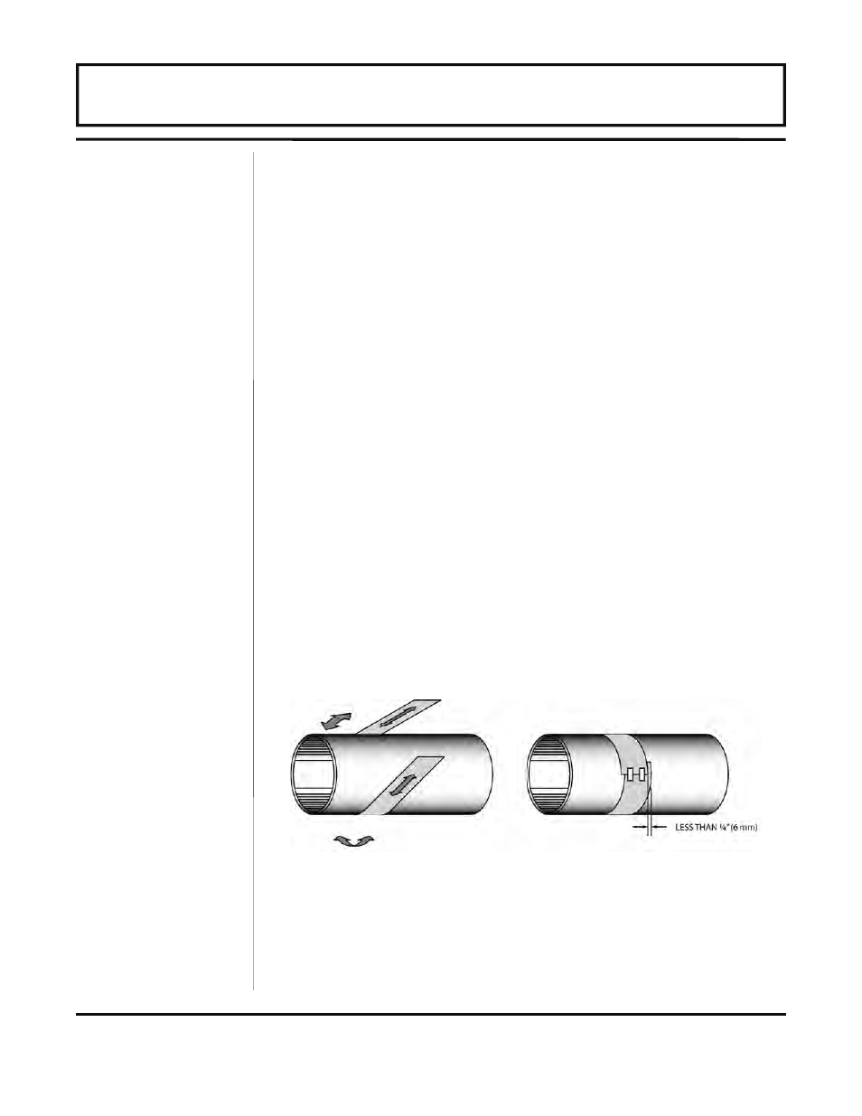
1. Wrap the paper around the pipe in the manner shown in Figure
2.9. Align the paper ends to within 1/4 inch (6 mm).
2. Mark the intersection of the two ends of the paper to indicate the
circumference. Remove the template and spread it out on a flat
surface. Fold the template in half, bisecting the circumference.
See Figure 2.10 on page 2.14.
Z-Mount
Transducer
Installation
Figure 2.9 — Paper Template Alignment
PART 2 - TRANSDUCER & RTD INSTALLATION