Datamax-O'Neil A-Class Mark II Operator’s Manual User Manual
Page 75
A-Class Mark II
65
Diagnostics (continued)
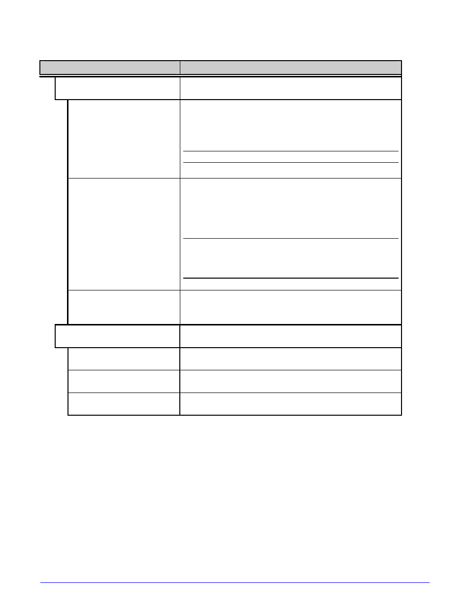
Menu Item
Details
TEST GPIO
Tests the Applicator Interface CCA’s GPIO function,
where:
MONITOR GPIO INPUT
SOP FEED PAUSE REPRT
1 1 1 1
i1 i2 i3 i4 i5 i6
1 1 1 1 1 1
Displays input signal logic values for Start of Print
(SOP), Feed, Pause, Reprint (REPRT), and six
unassigned input lines. (The values given here are
examples only.)
Unconnected lines may display a zero or one.
TEST GPIO OUTPUT
EP RL SR MO RO DR OF
1 1 1 1 1 1 1
o1 o2 o3 o4 o5 o6
1 1 1 1 1 1
Displays output signal logic values for End of Print
(EP), Ribbon Low (RL), Service Required (SR), Media
Out (MO), Ribbon Out (RO), Data Ready (DR), Option
Fault (OF), and six unassigned output lines. (The
values given here are examples only.)
To change an output signal, cursor over the
displayed state to select and then toggle it using
the keypad, except Data Ready which cannot be
toggled.
PRINT SIGNAL INFO
Prints a reference label (see Appendix D) containing
GPIO signal names, pin and port assignments,
programmed settings, and current signal states.
TEST RFID
Tests RFID, where:
TAG DATA
Reads the data encoded on an RFID tag.
DEVICE VERSION
Displays the type and version of the encoding device.
TAG ID – HF ONLY
Reads then displays the High Frequency Tag ID
number.