Datamax-O'Neil A-Class Mark II Operator’s Manual User Manual
Page 147
A-Class Mark II
137
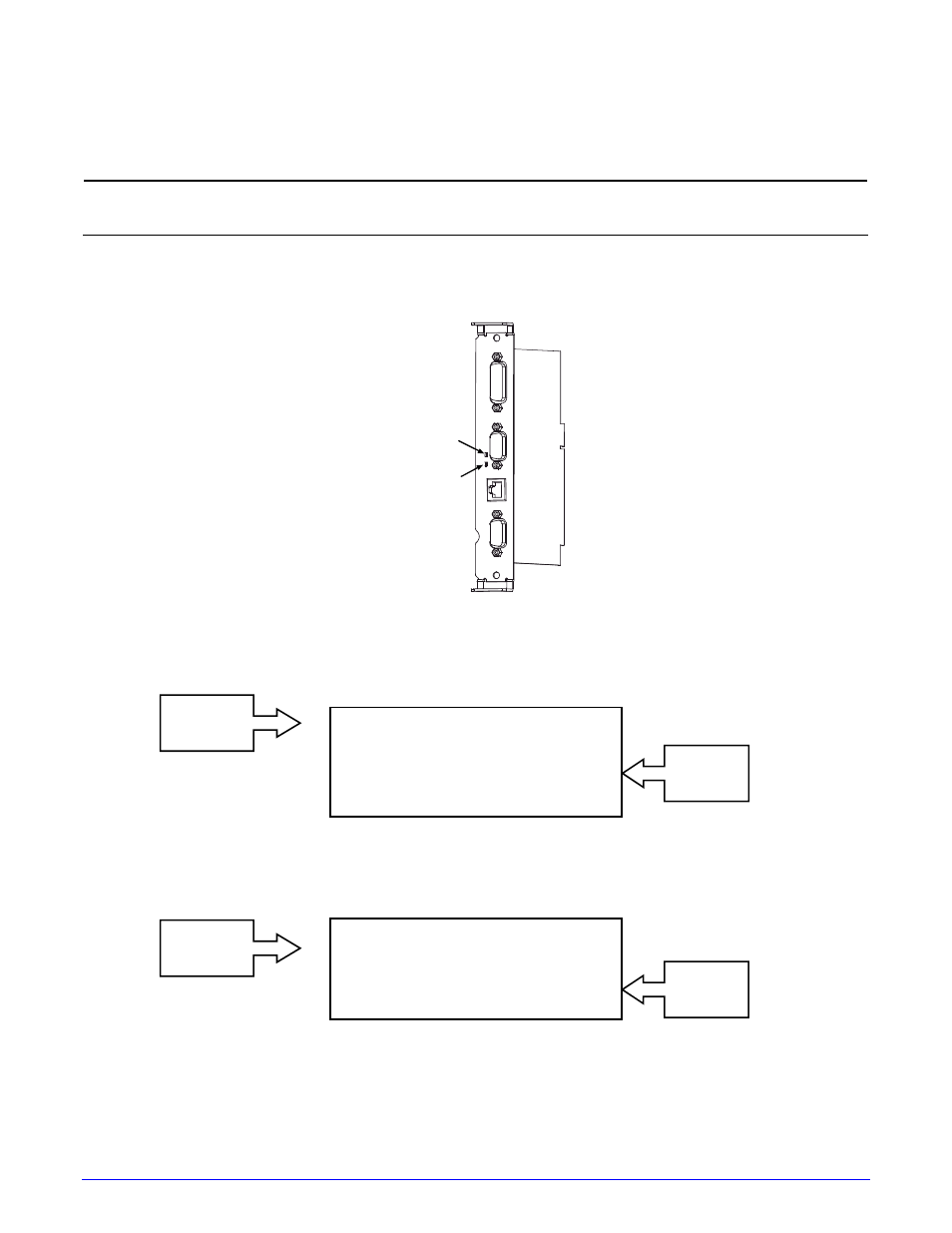
GPIO A
Signals
GPIO B
Signals
GPIO A
Signals
GPIO B
Signals
Indicators and Monitors
Real-time verification of settings and activity of the GPIO ports is available via displayed and
printed information:
Unused, non-connected inputs and outputs will have an indeterminate state and assume
a value of 1 or 0.
Indicators: Sampled every millisecond, incoming (IN) and outgoing (OUT) signal activity can
be observed on the card, where LED color changes correspond to signal state changes.
Signal Out
Signal In
Input Monitors: Binary input signal states can be viewed (see Section 4.2.6, TEST GPIO /
MONITOR GPIO INPUT) in the following format:
SOP FEED PAUSE REPRT
1 1 0 0
i1 i2 i3 i4 i5 i6
0 1 0 1 1 1
Output Monitors: Binary output signal states can be viewed (see Section 4.2.6, TEST GPIO /
MONITOR GPIO OUTPUT) in the following format:
EP RL SR MO RO DR OF
0 0 0 0 0 0 0
o1 o2 o3 o4 o5 o6
0 0 0 0 0 0
- MF8I 270 User Guide (20 pages)
- MF8I Installation Guide (18 pages)
- MF8I Truck Mount Cable (2 pages)
- MF8I Locking Mounting Bracket (2 pages)
- MF8I Economy Mounting Bracket (2 pages)
- MF8I AN-15 (Line Printer and Easy Print Modes) (7 pages)
- MF8I AN-16 (Single Byte Character Set Font File Format) (8 pages)
- MF8I Quick Reference Programming Guide (72 pages)
- MF8I Configuration Program Installation (1 page)
- MF8I Bluetooth Management Component for Wavelink Avalanche (10 pages)
- A-Class Mark II Installation (2 pages)
- A-Class Mark II DMXrfNetIII (16 pages)
- A-Class Mark II DMXrfNetII (16 pages)
- A-Class Mark II RFID Quick Start Guide (6 pages)
- A-Class Mark II Programmer’s Manual (334 pages)
- ANDES 3 User Guide (32 pages)
- ANDES 3 Quick Start Guide (2 pages)
- ANDES Series Programmer’s Manual (67 pages)
- APEX 2 User Guide (28 pages)
- APEX 2 Quick Start Guide (2 pages)
- APEX 3 User Guide (27 pages)
- APEX 3 Quick Start Guide (2 pages)
- APEX 4 User Guide (30 pages)
- APEX 4 Quick Start Guide (2 pages)
- E-Class Mark III Operator’s Manual (90 pages)
- E-Class Mark III 4xxxxxxx Operator’s Manual (58 pages)
- E-Class Mark III 3xxxxxxx Operator’s Manual (58 pages)
- E-Class Mark III Paper Menu (7 pages)
- E-Class Mark III DPL Programmer’s Manual (296 pages)
- E-Class Mark III Printhead Bracket and Screw Upgrade (11 pages)
- H-Class Operator’s Manual (180 pages)
- Static brush (2 pages)
- H-Class Media Retainer (1 page)
- H-Class Thermal Transfer Option (12 pages)
- H-Class RFID Option (8 pages)
- H-Class Powered Internal Rewind Option (10 pages)
- H-Class Internal Rewind Option (6 pages)
- H-Class Present Sensor Option (8 pages)
- H-Class Peel & Present Option (8 pages)
- H-Class Linear Scanner Option (26 pages)
- H-Class HD Peel & Present Option (10 pages)
- H-Class HD Cutter Option (12 pages)
- H-Class GPIO Option (14 pages)
- H-Class Cutter Option (10 pages)