1 power connector – ZyXEL Communications XGS-4728F User Manual
Page 39
Chapter 3 Hardware Overview
XGS-4728F User’s Guide
39
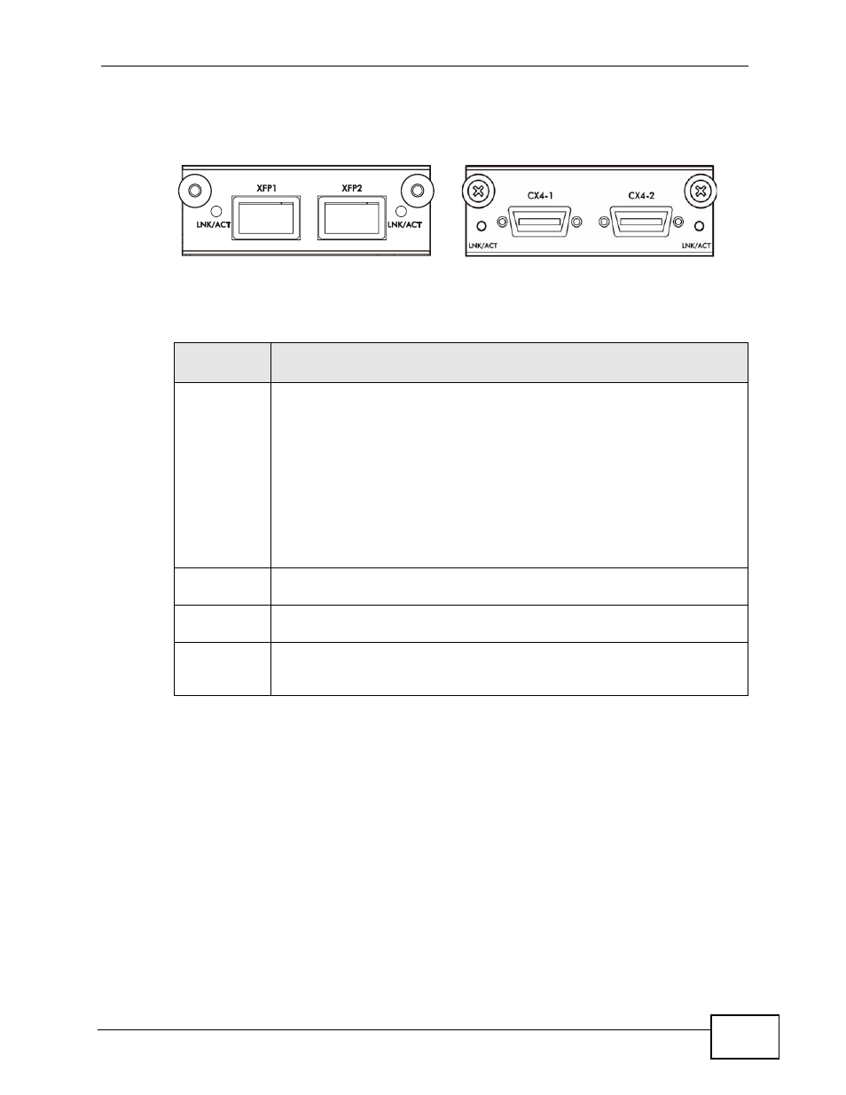
The following figure shows the front panel of the EM-422 and EM-412 modules.
Figure 15 The Front Panel of the EM-422 and EM-412 Modules
The following table describes the ports on the rear panel.
3.2.1 Power Connector
Make sure you are using the correct power source as shown on the panel.
To connect the power to the Switch, insert the female end of power cord to the
power receptacle on the rear panel. Connect the other end of the supplied power
cord to a power outlet. Make sure that no objects obstruct the airflow of the fans.
The Switch’s AC unit requires a power supply of 100~240 VAC, 0.8 A.
The Switch’s DC version requires a power supply of -48 VDC to -60 VDC, 2.3 A
max, no tolerance.
Table 2 Panel Connections
CONNECTO
R
DESCRIPTION
Optional two
XFP or CX4
Ports
These ports are available when you install an EM-422 or ES-412 in the
optional uplink module (B in the figure above). Both the EM-422 and ES-
412 are used to connect your switch to other high-speed Ethernet
switches for stacking in you network.
• For EM-422 connection: Use 10 Gigabit Small Form Factor Pluggable
(XFP) transceivers to connect 1000Base-X fiber-optic cables to these
ports. See
for information on installing and removing transceivers.
• For EM-412 connection: Use 10GBase-CX4 cables to connect to these
ports.
See the EM-422 and EM-412 User’s Guides for more information.
Two stacking
ports
Connect these ports to other XGS-4728F switches for stacking using
stacking cables.
Management
Port
Connect to a computer using an RJ-45 Ethernet cable for local
configuration of the Switch.
Console Port Only connect this port to your computer (using an RS-232 cable) if you
want to configure the Switch using the command line interface (CLI) via
the console port.
EM-412
EM-422