Toshiba M10 User Manual
Page 375
4.34 TFT FL (Model 15.0 UXGA SHARP LQ150U1LW13)
4 Replacement Procedures
Satellite Pro M10 Series Maintenance Manual (960-431)
4-163
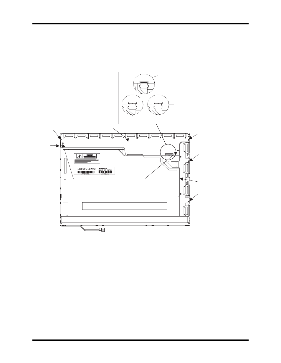
7. Secure the TCP of the source PCB with three screws.
8. Secure the TCP of the gate PCB with two screws.
9. Connect the FPC to the connector on the source PCB.
Screw
Screw
Pin
*
Pin
*
Screw
Screw
Screw
Tighten the screws with 1.0 kgf•cm of torque.
*
Align the holes on the PCBs with the pins.
Gate PCB
Source PCB
Make sure the latch secures the connector correctly.
See the notches on both the edge of the FPC, and
see the contour of the connector.
Insert the FPC into the connector firmly. The FPC
must have no inclination. Lock the connector firmly.
NG: The FPC has inclination.
NG: The FPC does not connect firmly.
Figure 4-142 Securing the TCPs and connecting the FPC
- Libretto W100 (117 pages)
- R400 (4 pages)
- Qosmio Personal Computer X500 (277 pages)
- Computer L300D (186 pages)
- Satellite P300-SE3 (2 pages)
- NB250 (130 pages)
- NB250 (138 pages)
- NB250 (197 pages)
- Tecra M3 (2 pages)
- Tecra M3 (236 pages)
- Tecra M3 (256 pages)
- PORT (243 pages)
- Tecra M9-ST5511 (8 pages)
- 6100 (266 pages)
- PORTABLE PERSONAL COMPUTER L500 (188 pages)
- F15 (328 pages)
- Satellite M60-S811TD (7 pages)
- SATELLITE L300D (165 pages)
- SATELLITE L300D (174 pages)
- SATELLITE L300D (187 pages)
- M300 (218 pages)
- A40 Series (286 pages)
- A50 (211 pages)
- Satellite 5205 Series (312 pages)
- SATELLITE A65 (242 pages)
- 510D (15 pages)
- PSA20 (244 pages)
- M40 (262 pages)
- 3500 (24 pages)
- M30 (236 pages)
- Satellite A105-S4344 (11 pages)
- Satellite A135-S2286 (11 pages)
- 2000 (76 pages)
- M400 (298 pages)
- M400 (2 pages)
- Satellite A205-S7458 (5 pages)
- Magnia Z300 (145 pages)
- Magnia Z300 (40 pages)
- Magnia Z300 (109 pages)
- Magnia Z300 (272 pages)
- Magnia Z300 (270 pages)
- X200 (233 pages)
- SATELLITE A665 (234 pages)
- SATELLITE A200 (186 pages)