Toshiba M10 User Manual
Page 232
4 Replacement Procedures
4.4 Slim Select Bay Module
4-20
Satellite Pro M10 Series Maintenance Manual (960-431)
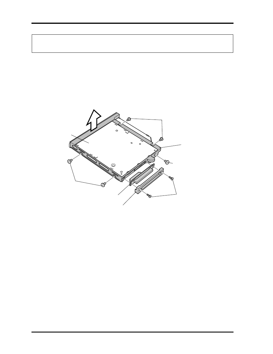
NOTE: If you are going to replace an ODD, follow the steps below to disassemble the
slim select bay module.
3. Remove two M2
×8 black screws securing the connector cover.
4. Remove the connector cover and ODD interface board.
5. Remove five M2
×3 thin silver flat-head screws securing the ODD bracket.
6. Remove the ODD bracket.
M2
×
3 thin silver flat-head screws
M2
×
8 black screws
M2
×
3 thin silver flat-head screws
ODD bracket
ODD interface board
Connector cover
ODD
M2
×
3 thin silver flat-head screws
Figure 4-10 Disassembling the optical disk drive
See also other documents in the category Toshiba Computers:
- Libretto W100 (117 pages)
- R400 (4 pages)
- Qosmio Personal Computer X500 (277 pages)
- Computer L300D (186 pages)
- Satellite P300-SE3 (2 pages)
- NB250 (130 pages)
- NB250 (138 pages)
- NB250 (197 pages)
- Tecra M3 (2 pages)
- Tecra M3 (236 pages)
- Tecra M3 (256 pages)
- PORT (243 pages)
- Tecra M9-ST5511 (8 pages)
- 6100 (266 pages)
- PORTABLE PERSONAL COMPUTER L500 (188 pages)
- F15 (328 pages)
- Satellite M60-S811TD (7 pages)
- SATELLITE L300D (165 pages)
- SATELLITE L300D (174 pages)
- SATELLITE L300D (187 pages)
- M300 (218 pages)
- A40 Series (286 pages)
- A50 (211 pages)
- Satellite 5205 Series (312 pages)
- SATELLITE A65 (242 pages)
- 510D (15 pages)
- PSA20 (244 pages)
- M40 (262 pages)
- 3500 (24 pages)
- M30 (236 pages)
- Satellite A105-S4344 (11 pages)
- Satellite A135-S2286 (11 pages)
- 2000 (76 pages)
- M400 (298 pages)
- M400 (2 pages)
- Satellite A205-S7458 (5 pages)
- Magnia Z300 (145 pages)
- Magnia Z300 (40 pages)
- Magnia Z300 (109 pages)
- Magnia Z300 (272 pages)
- Magnia Z300 (270 pages)
- X200 (233 pages)
- SATELLITE A665 (234 pages)
- SATELLITE A200 (186 pages)