Example 2: virtual links, Configuring ospf for a virtual link on switch #1, Example 2: virtual links 86 – Nortel Networks WEB OS 212777 User Manual
Page 86: Figure 4-6, Configuring a virtual link 86
Web OS 10.0 Application Guide
86
n
Chapter 4: OSPF
212777-A, February 2002
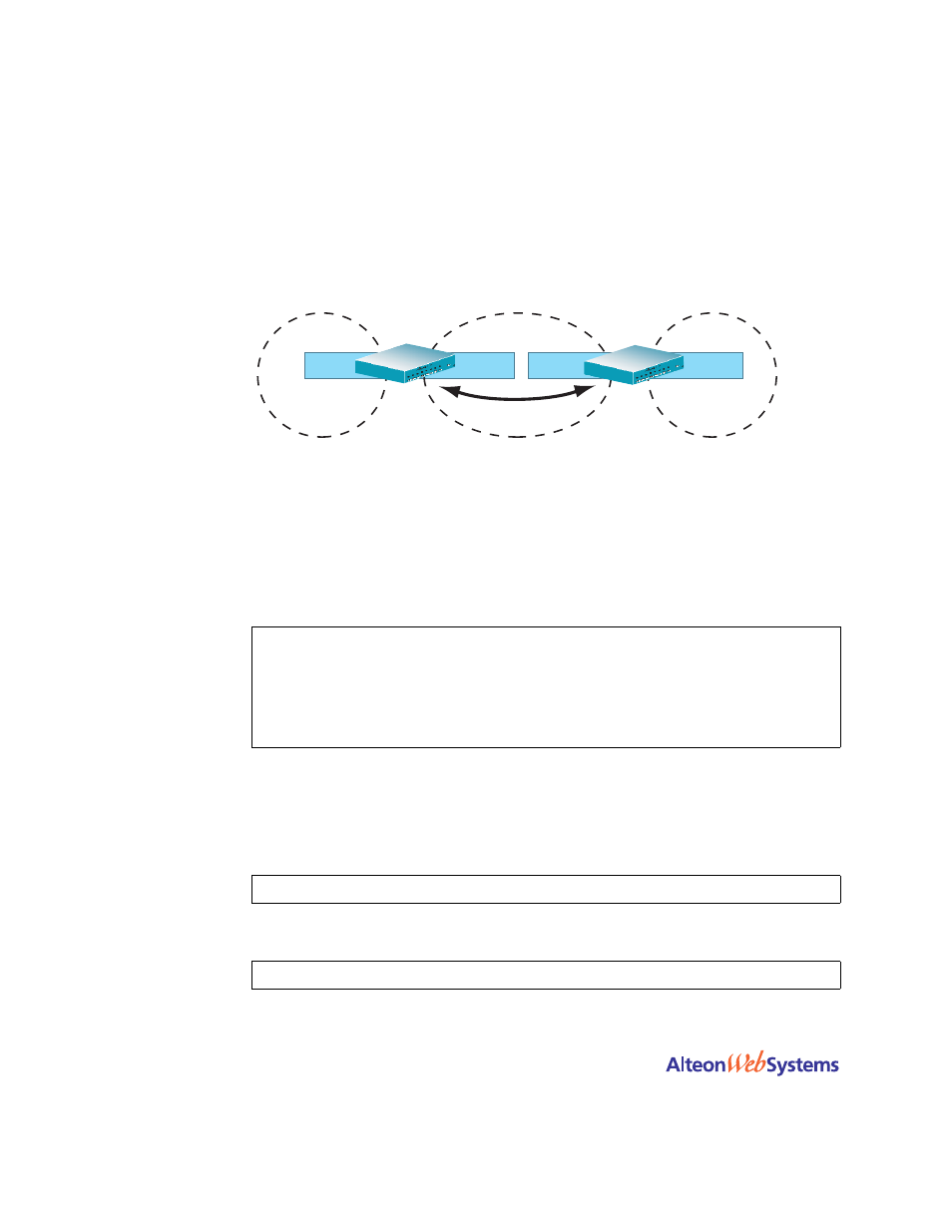
Example 2: Virtual Links
In the example shown in
, area 2 is not physically connected to the backbone as is
usually required. Instead, area 2 will be connected to the backbone via a virtual link through
area 1. The virtual link must be configured at each endpoint.
Figure 4-6 Configuring a Virtual Link
Configuring OSPF for a Virtual Link on Switch #1
1.
Configure IP interfaces on each network that will be attached to the switch.
In this example, two IP interfaces are needed on Switch #1: one for the backbone network on
10.10.7.0/24 and one for the transit area network on 10.10.12.0/24.
2.
Configure the router ID.
A router ID is required when configuring virtual links. Later, when configuring the other end
of the virtual link on Web Switch 2, the router ID specified here will be used as the target vir-
tual neighbor (
nbr
) address.
3.
Enable OSPF.
>> # /cfg/ip/if 1
(Select menu for IP interface 1)
>> IP Interface 1 # addr 10.10.7.1
(Set IP address on backbone network)
>> IP Interface 1 # enable
(Enable IP interface 1)
>> IP Interface 1 # ../if 2
(Select menu for IP interface 2)
>> IP Interface 2 # addr 10.10.12.0
(Set IP address on transit area network
)
>> IP Interface 2 # enable
(Enable interface 2)
>> IP Interface 2 # /cfg/ip/ospf/rtrid 10.10.10.1
(Set static router ID on Web switch 1)
>> IP # /cfg/ip/ospf/on
(Enable OSPF on Web switch 1)
Router ID:
10.10.10.1
Router ID:
10.10.14.1
Switch #1
Switch #2
Virtual Link 1
Area 0
(0.0.0.0)
IF 1
10.10.7.1
IF 2
10.10.12.1
Area 1
(0.0.0.1)
Backbone
Transit Area
IF 1
10.10.12.2
IF 2
10.10.24.1
10.10.7.0/24
Network
10.10.12.0/24
Network
10.10.24.0/24
Network
Area 2
(0.0.0.2)
Stub Area