Sharing/active-active failover, Sharing/active-active failover 260, Figure 11-7: active-active high availability 260 – Nortel Networks WEB OS 212777 User Manual
Page 260: Table 11-2, Sharing active-active failover 260
Web OS 10.0 Application Guide
260
n
Chapter 11: High Availability
212777-A, February 2002
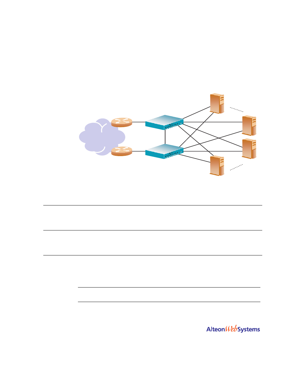
Sharing/Active-Active Failover
Web OS supports sharing of interfaces at both Layer 3 and Layer 4, as shown in
With sharing, an IP interface or a VIP address can be active simultaneously on multiple
switches, enabling active-active operation as shown in
.
Figure 11-7 Active-Active High Availability
When sharing is used, incoming packets are processed by the switch on which they enter the
virtual router. The ingress switch is determined by external factors, such as routing and Span-
ning Tree configuration.
N
OTE
–
Sharing cannot be used in configurations where incoming packets have more than one
entry point into the virtual router—for example, where a hub is used to connect the switches.
Table 11-2 Sharing Active-Active Failover
Web Switch 1 Master-Active VR 1
VRID 2
VIP: 205.178.13.226
MAC address 00-00-5E-OO-01-02
Backup-Active VR 2
VRID 4
VIP: 205.178.13.240
MAC address 00-00-5E-OO-01-04
Master-Active VR 3
VRID 6
VIP: 205.178.13.110
MAC address 00-00-5E-OO-01-06
Web Switch 2 Backup-Active VR 1
VRID 2
VIP: 205.178.13.226
MAC address 00-00-5E-OO-01-02
Master-Active VR 2
VRID 4
VIP: 205.178.13.240
MAC address 00-00-5E-OO-01-04
Backup-Active VR 3
VRID 6
VIP: 205.178.13.110
MAC address 00-00-5E-OO-01-06
Internet
Router
Router
Backup-Active VR 1
Master-Active VR 2
Backup-Active VR 3
Master-Active VR 1
Backup-Active VR 2
Master-Active VR 3
Web Switch 1
Web Switch 2