Active-active vir and vsr configuration, Active-active vir and vsr configuration 265 – Nortel Networks WEB OS 212777 User Manual
Page 265
Web OS 10.0 Application Guide
Chapter 11: High Availability
n
265
212777-A, February 2002
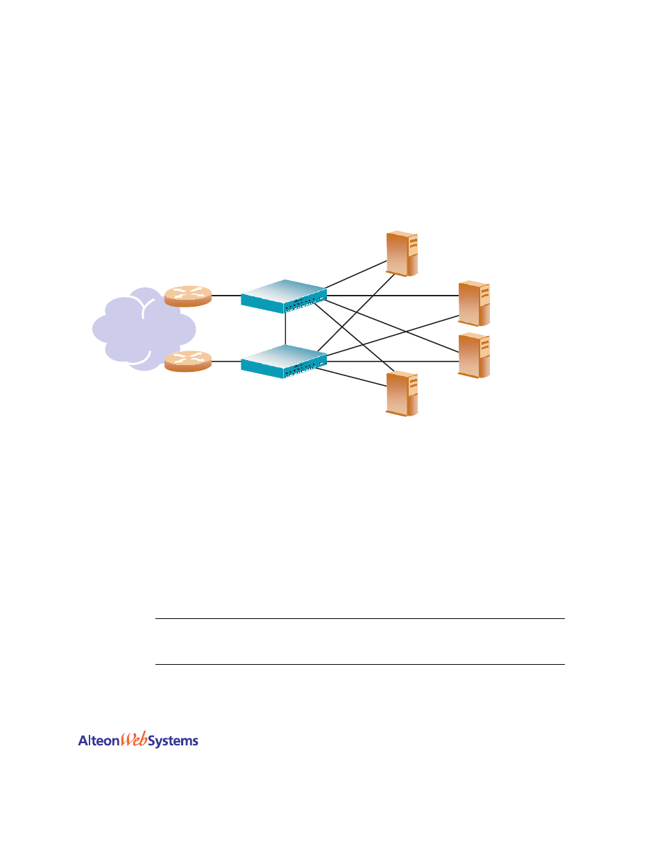
Active-Active VIR and VSR Configuration
two Alteon Web switches are used as VRRP routers in an active-active configura-
tion implementing a virtual server router. As noted earlier, this is the preferred redundant con-
figuration.
Figure 11-9 Active-Active High-Availability Configuration
Although this example shows only two switches, there is no limit on the number of switches
used in a high availability configuration. It is possible to implement an active-active configura-
tion and perform load sharing between all of the VRRP-capable switches in a LAN.
In this configuration, when both switches are healthy, the load balanced packets are sent to the
virtual server IP address, resulting in higher capacity and performance than when the switches
are used in an active-standby configuration.
The switch on which a frame enters the virtual server router is the one that processes that
frame. The ingress switch is determined by external factors, such as routing and STP settings.
N
OTE
–
Each VRRP-capable switch is autonomous. There is no requirement that the switches
in a virtual router be identically configured. Different switch models with different numbers of
ports and different enabled services may be used in a virtual router.
Internet
Router
Router
Backup-Active
VRID 2
VIP: 205.178.13.226
MAC address 00-00-5E-00-01-02
Server 4
RIP 1: 205.178.13.104
Master-Active
VRID 2
VIP: 205.178.13.226
MAC address 00-00-5E-00-01-02
Server 3
RIP 1: 205.178.13.103
Server 2
RIP 1: 205.178.13.102
Server 1
RIP 1: 205.178.13.101
Web Switch 1
Web Switch 2