Input signal table objects, Table c-14. not supported for the t – Paradyne 7112 User Manual
Page 126
MIB Descriptions
C-24
7112-A2-GB20-10
March 1998
Table C-13.
Synchronous Port Table Objects (2 of 2)
Object, OID, Access
Setting/Contents
Description
rs232SyncPortMode
(rs232SyncPortEntry 12 )
1.3.6.1.2.1.10.33.4.1.12
read-write
Specifies the port’s mode of
data transfer.
Supports only the following
value:
fdx(1) – Full-duplex
rs232SyncPortMinFlags
(rs232SyncPortEntry 14 )
1.3.6.1.2.1.10.33.4.1.14
read-write
Specifies the minimum
number of flag patterns the
port needs in order to
recognize the end of one
from and the start of
another.
The only valid value is 2.
The following is not supported:
H
rs232SyncPortIdle Pattern
(rs232SyncPortEntry 13 )
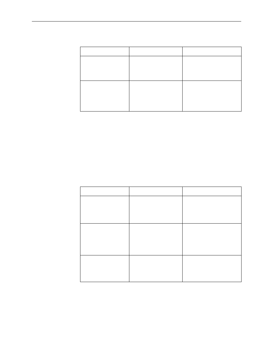
Input Signal Table Objects
The Input Signal Table Objects contains entries for the input signals that can be
detected by the unit for the synchronous user data port. Clarification for objects
contained in this table as it applies to the unit is provided below.
Table C-14.
Input Signal Table Objects
Object, OID, Access
Description
Setting/Contents
rs232InSigName
(rs232InSigEntry 2 )
1.3.6.1.2.1.10.33.5.1.2
read-only
Contains the identification
of a hardware input signal.
Supports only the following
values:
rts(1) – Request To Send
dtr(4) – Data Terminal Ready
rs232InSigState
(rs232InSigEntry 3 )
1.3.6.1.2.1.10.33.5.1.3
read-only
Contains the current signal
state.
Supports only the following
values:
on(2) – The signal is asserted.
off(3) – The signal is
deasserted.
rs232InSigChanges
(rs232InSigEntry 4 )
1.3.6.1.2.1.10.33.5.1.4
read-only
Indicates the number of
times that a signal has
changed from on to off, or
off to on.
The object is incremented
each time that the signal is
sampled (every 100 ms) and
the signal state is different
from the previous state.