Yaskawa MP900 Series Machine Controller Programming Panel for Simple Operation User Manual
Page 134
7.2 Manipulating Module Configuration Definitions
7-5
7
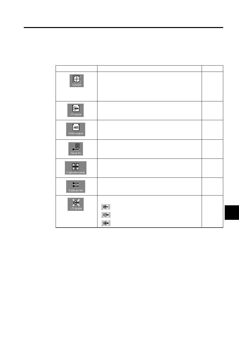
2. Data Display
The icon each data item in the Rack Configuration can be switched. The following icons
will be displayed for corresponding Modules when the display mode is selected.
∗ 1.
For the duplication of the communication path of the 215IF Modules,
the Modules must be in a duplicate configuration.
∗ 2.
It is not possible to make I/O disable settings in simple operation
mode. Set the mode to standard mode.
Display
Description
Remarks
The allocation status of the Module will be displayed. A green or red
lamp appearing on the lower left side of the Module has the follow-
ing meaning.
• Green: Indicates that the Module has been allocated.
• Red: Indicates that the detailed data definition of the Module has not
been set.
The range of register numbers allocated to the Module will be dis-
played if the Module needs I/O register allocation.
A green lamp will appear on the lower left side of the Module.
The range of motion register numbers allocated to the Motion Mod-
ule will be displayed.
The circuit number will be displayed for the Communications Mod-
ule.
The servo number will be displayed for the Motion Module.
Not used
MP920
only
The duplicate line status of the Communications Module will be dis-
played if the 215IF Module is used.
*1
MP920
only
The I/O disable status of the I/O Module will be displayed.
*2
•
: Indicates that input is disabled.
•
: Indicates that output is disabled.
•
: Indicates that both input and output are disabled.