3 ) programming example – Yaskawa MP900 Series Ladder Programming Manual User Manual
Page 302
5.10 System Function Instructions
5.10.3 Trace (TRACE)
5-233
Instructions
5
The parameters are described in the following table.
The status configuration is shown below.
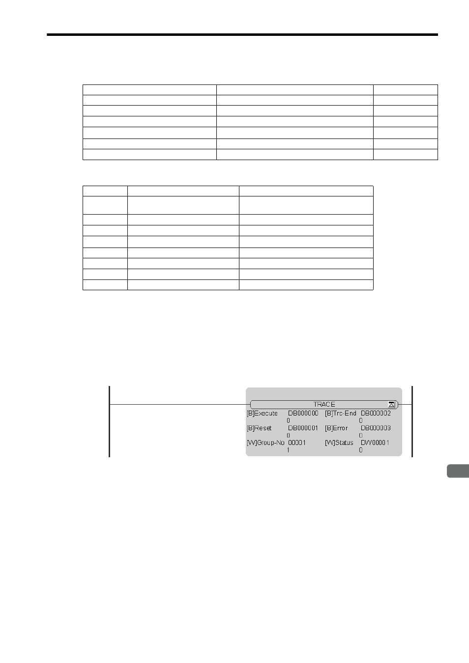
( 3 ) Programming Example
In the following programming example, the definition for trace group number 1 is used to execute a trace. The trace
starts when DB000000 turns ON.
Set the data trace definition for trace group number 1 on the MPE720 in advance. Make sure to set the sampling
condition to Program.
Parameter Name
Description
I/O
Trace execution command (Execute)
Trace execution begins when this command turns ON.
IN
Trace reset command (Reset)
Trace execution is reset when this command turns ON.
IN
Trace group No. (Group-No)
Trace group No. specification (1 to 4)
IN
Trace end (Trc-End)
Turns ON when the trace ends.
OUT
Error
Turns ON when an error occurs.
OUT
Status
Trace execution status
OUT
Bit
Name
Remarks
0
Trace data full
Turns ON after once going through the data
trace memory of the specified group.
1 to 7
Reserved for system.
–
8
No trace definition
The function will not be executed.
9
Group No. error
The function will not be executed.
10 to 12
Reserved for system.
–
13
Execution timing error
The function will not be executed.
14
Reserved for system.
–
15
Reserved for system.
–