8 phase lead lag (llag) – Yaskawa MP900 Series Ladder Programming Manual User Manual
Page 233
5.8 DDC Instructions
5.8.8 Phase Lead Lag (LLAG)
5-164
5.8.8 Phase Lead Lag (LLAG)
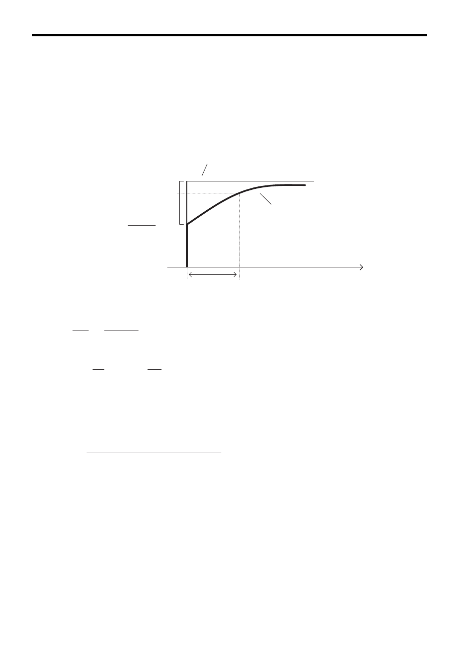
( 1 ) Operation
The LLAG instruction calculates the phase lead and lag according to predefined parameters in a parameter table. The
input value to the LLAG instruction can be an integer or real number. Double-length integers cannot be used.
The structure of the parameter table is different for integers and real numbers.
The LLAG operation in the figure shown above can be expressed by the formula shown below.
Therefore,
The following operation is performed internally by the LLAG instruction, where dt = Ts, dY = Y – Y’, and dX = X –
X’.
In the formula shown below, Y’ is the previous output value, X’ is the previous input value, Ts is the scan time set
value*, and REM is the remainder.
∗ The unit for Ts is the same as the unit for T1.
When IRST (LLAG reset) is closed, Y outputs 0, REM outputs 0, and X outputs 0.
Output value Y for
LLAG instruction
Input value X for
LLAG instruction
Time (t)
Phase lag time constant T1
Approx. 63% →
T2 + Ts
T1 + Ts
X →
100%
0%
=
1 + T1 × s
Y(s)
X(s)
1 + T2 × s
T1
× + Y
dY
dt
T2
× + X
dX
dt
=
Y =
T1 × Y' + (T2 + Ts) × X −T2 × X' + REM
T1 + Ts