1 connecting the hardware, Ladder program development flow – Yaskawa MP900 Series Ladder Programming Manual User Manual
Page 30
3.1 Ladder Program Design Procedures
3.1.1 Connecting the Hardware
3-3
Ladder Program Development Flow
3
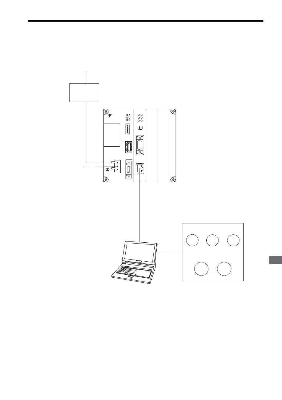
3.1.1 Connecting the Hardware
The flow of ladder program development that is described in this chapter is based on the following system configura-
tion.
∗ In this chapter, M registers in the Machine Controller are used to simulate virtual I/O devices in the example system.
In practice, the input and output signals would be connected to I/O Modules on the Machine Controller, and the ladder program
would be created using I and O registers.
Virtual I/O Devices*
(Entered on MPE720.)
SW1
SW2
SW3
MB00000 MB00001
Lamp 1
Lamp 2
MB00010
MB00011
Ethernet cable
PC running MPE720
24-VDC
power supply
Machine Controller
MB00002
DC24V
DC 0V
MP2300
YASKAWA
TEST
RDY
ALM
TX
RUN
ERR
BAT
MON
CNFG
INT
SUP
STOP
SW1
OFF ON
BATTERY
CPU I/O
M-I/II
218IF-01
ERR
COL
RX
RUN
STRX
TX
INIT
TEST
ON
OFF
PORT
10Base-T
Optional Module
Optional Module