2 ) format – Yaskawa MP900 Series Ladder Programming Manual User Manual
Page 264
5.8 DDC Instructions
5.8.13 Pulse Width Modulation (PWM)
5-195
Instructions
5
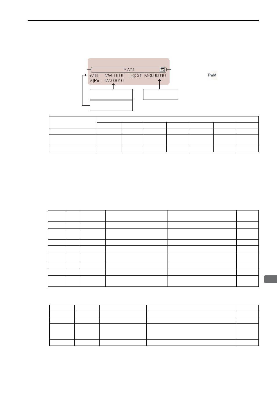
( 2 ) Format
∗ C and # registers cannot be used.
[ a ] Ranges of Input and Output Values
The input value must be between -10,000 and 10,000 in units of 0.01%.
If the input exceeds this range, processing is performed for the upper limit (10,000) and the lower limit (-10,000).
The output value is set to 1 when the PWM output is ON, or to 0 when the PWM output is OFF.
[ b ] Parameter Table Configuration
∗ The relay input and output bits are assigned as given below. (Close = Bit change to 1 (ON), Open = Bit change to 0
(OFF))
Parameter Name
Applicable Data Types
B
W
L
F
A
Index
Constant
Input value (In)
×
{
×
×
×
{
{
First address of
parameter table (Prm)
×
×
×
×
{
*
{
{
Output value (Out)
{
*
×
×
×
×
{
×
First address of
parameter table
Output value
Input value
Icon:
Key entry: PWM
Address
Data
Type
Symbol
Name
Specification
I/O
0
W
RLY
Relay I/O
Relay inputs and relay outputs
*
IN/OUT
1
W
RWMT
PWM cycle
PWM cycle (1 ms)
Range: 1 to 32,767 ms
IN
2
W
ONCNT
ON output setting timer
ON output setting timer (1 ms)
OUT
3
W
CVON
ON output counting timer
ON output counting timer (1 ms)
OUT
4
W
CVONREM
ON output counting timer remainder
ON output counting timer remainder
(0.1 ms)
OUT
5
W
OFFCNT
OFF output setting timer
OFF output setting timer (1 ms)
OUT
6
W
CVOFF
OFF output counting timer
OFF output counting timer (1 ms)
OUT
7
W
CVOFFREM
OFF output counting timer remain-
der
OFF output counting timer remainder
(0.1 ms)
OUT
Bit
Symbol
Name
Specification
I/O
0
PWMRST
PWM reset bit
This input is closed to reset the PWM operation.
IN
2 to 7
–
(Reserved.)
Spare input relays
IN
8
PWMOUT
PWM output
PWM output
(The output value is set to 1 when the output is ON, or
to 0 when the output is OFF.)
OUT
9 to F
–
(Reserved.)
Spare output relays
OUT