2 ) format – Yaskawa MP900 Series Ladder Programming Manual User Manual
Page 220
5.8 DDC Instructions
5.8.5 PD Control (PD)
5-151
Instructions
5
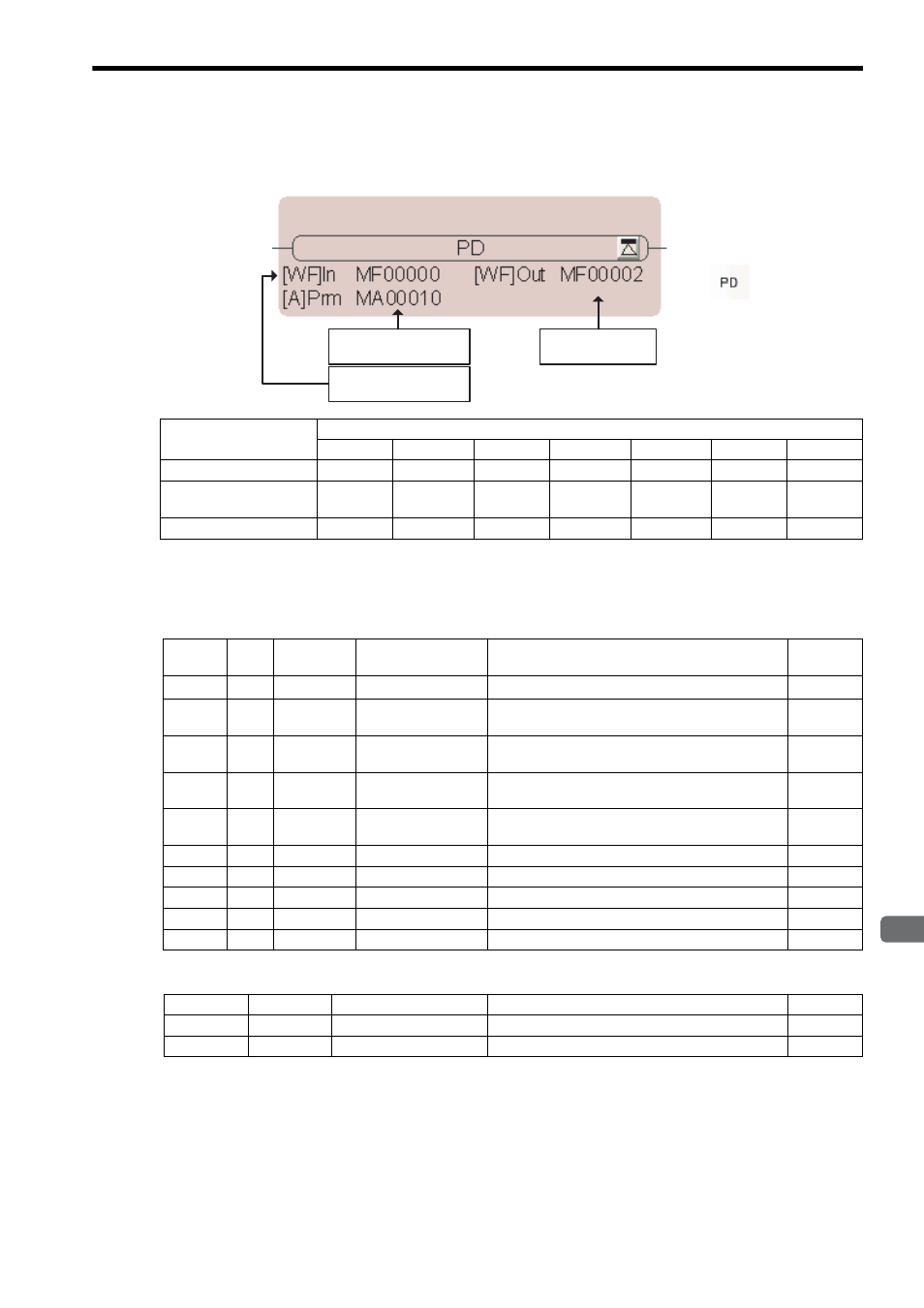
( 2 ) Format
∗ C and # registers cannot be used.
[ a ] Parameter Table Configuration for PD Instruction with Integers
∗ The relay input and output bits are assigned as given below.
First address of
parameter table
Output value
Input value
Icon:
Key entry: PD
Parameter Name
Applicable Data Types
B
W
L
F
A
Index
Constant
Input value (In)
×
{
×
{
×
{
{
First address of
parameter table (Prm)
×
×
×
×
{
*
{
{
Output value (Out)
×
{
*
×
{
*
×
{
×
Address
Data
Type
Symbol
Name
Specification
I/O
0
W
RLY
Relay I/O
Relay inputs and relay outputs
*
IN/OUT
1
W
Kp
P gain
Gain for the P compensation
(A gain of 1 is equivalent to 100.)
IN
2
W
Kd
D gain
Gain for the input to the differential circuit
(A gain of 1 is equivalent to 100.)
IN
3
W
Td1
Differential time for
divergence
Differential time used when the input diverges (ms)
IN
4
W
Td2
Differential time for
convergence
Differential time used when the input converges (ms)
IN
5
W
UL
PD upper limit
Upper limit for the P + D compensation
IN
6
W
LL
PD lower limit
Lower limit for the P + D compensation
IN
7
W
DB
PD output dead zone
Dead zone width for the P + D compensation
IN
8
W
Y
PD output
PD compensation output (output to Out)
OUT
9
W
X
Input value storage
Storage of current input value
OUT
Bit
Symbol
Name
Specification
I/O
0 to 7
–
(Reserved.)
Spare input relays
IN
8 to F
–
(Reserved.)
Spare output relays
OUT