Yaskawa VS-616G5 Modbus Plus Communication Card User Manual
Page 94
Data Registers
A-14
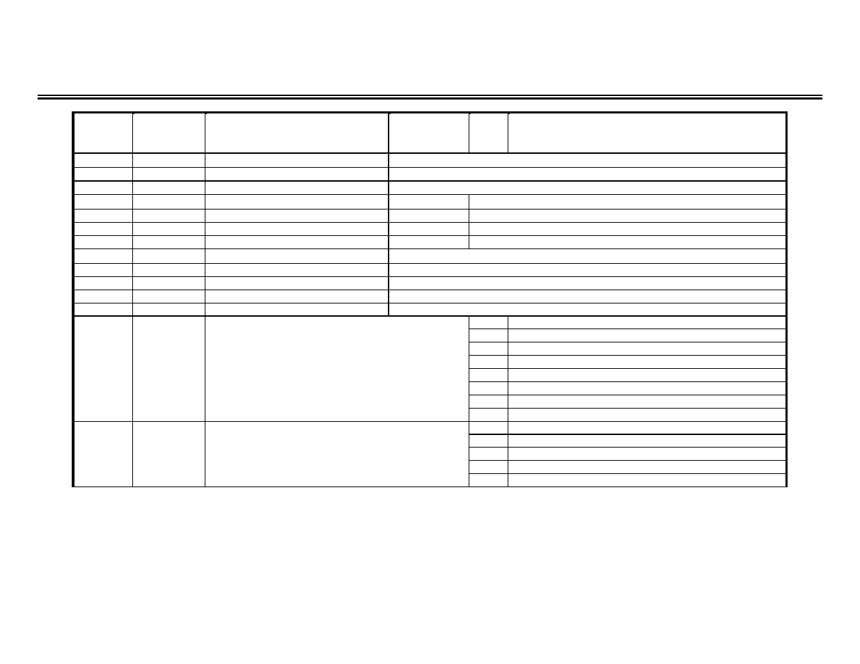
Drive Parameter Registers (U1-xx / Monitor Only)
REGISTER PARAMETER
PARAMETER
PARAMETER
BIT
LIMITS / DESCRIPTION
(in hex)
FUNCTION
SETTING
NO.
020h
U1-01
Frequency Reference
Frequency Reference of drive (0.1 Hz) (1)
021h
U1-02
Output Frequency
Output Frequency of drive (0.1 Hz) (1)
022h
U1-03
Output Current
10V/Drive rated current (2)
023h
U1-04
Control Method
0
V/f Control
1
V/f with PG Feedback
2
Open Loop Vector
3
Flux Vector
024h
U1-05
Motor Speed
Motor Speed (in 0.1 Hz)
025h
U1-06
Output Voltage
Output Voltage (in 0.1 V)
026h
U1-07
DC Bus Voltage
DC Bus Voltage (in 1 V)
027h
U1-08
Output Power
Output Power (in 0.1 kW)
028h
U1-09
Torque Reference
Torque Reference (in 0.1%)
029h
U1-10
Input Terminal Status
0
Input Terminal 1 closed
1
Input Terminal 2 closed
2
Input Terminal 3 closed
3
Input Terminal 4 closed
4
Input Terminal 5 closed
5
Input Terminal 6 closed
6
Input Terminal 7 closed
7
Input Terminal 8 closed
02Ah
U1-11
Output Terminal Status
0
Control Circuit terminals 9 & 10: “Closed”
1
Control Circuit terminals 25 & 27: “Closed”
2
Control Circuit terminals 26 & 27: “Closed”
3-6
not used
7
Control Circuit terminals 18 & 20: “Closed”
Notes:
(1) Scaling depends on the setting of o1-03.
(2) Display unit = 0.01A for models CIMR-G5U20P4 thru 25P5 and 40P4 thru 45P5; display unit = 0.1A for models 27P5 thru 2075 and 47P5 thru 4300.