Yaskawa VS-616G5 Modbus Plus Communication Card User Manual
Page 106
Data Registers
A-26
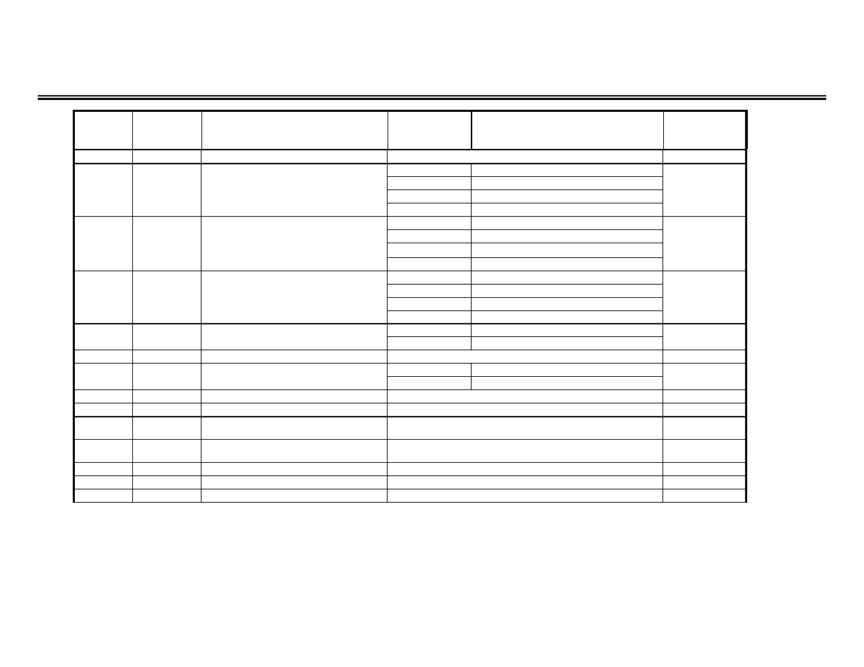
Drive Parameter Registers (Read/Write) – continued
REGISTER PARAMETER
PARAMETER
PARAMETER
LIMITS / DESCRIPTION
INITIAL
(in hex)
FUNCTION
SETTING
VALUE
380h
F1-01
Encoder (PG) Constant
0 to 60000 ppr
600
381h
F1-02
Operation Selection at PG Open
0
Ramp to stop
Circuit
1
Coast to stop
1
2
Fast-stop
3
Alarm only
382h
F1-03
Operation Selection at Overspeed
0
Ramp to stop
1
Coast to stop
1
2
Fast-stop
3
Alarm only
383h
F1-04
Operation Selection at Speed
0
Ramp to stop
Deviation
1
Coast to stop
3
2
Fast-stop
3
Alarm only
384h
F1-05
PG Rotation
0
Counter-clockwise
0
1
Clockwise
385h
F1-06
PG Division Rate (PG Pulse Monitor)
1 to 132 (effective only with PG-B2 control board)
1
386h
F1-07
Integral Value during Accel/Decel
0
Disabled
0
Selection
1
Enabled
387h
F1-08
Overspeed Detection Level
0 to 120%
115
388h
F1-09
Overspeed Detection Delay Time
0.0 to 2.0 seconds
(1)
389h
F1-10
Excessive Speed Deviation
Detection Level
0 to 50%
10
38Ah
F1-11
Excessive Speed Deviation
Detection Delay Time
0.0 to 10.0 seconds
0.5
38Bh
F1-12
Number of PG Gear Teeth 1
0 to 1000
0
38Ch
F1-13
Number of PG Gear Teeth 2
0 to 1000
0
397h **
F1-14
PG Open Detection Time
0 to 10.0 seconds
2.0
Notes (for this page only):
(1) Initial Value differs depending on the control method (A1-02).
** note: out of numeric sequence