Mb+ board configuration – Yaskawa VS-616G5 Modbus Plus Communication Card User Manual
Page 14
3-4 Installation of the MB+ Board
MB+ Board Configuration
The MB+ board requires setup prior to operation. 8-position Dip switch SW1 must be set prior to
the application of input AC power to the VS-616G5. The states of these switches are read only on
power-up.
The MB+ board SW1 switches are defined in the following table:
Switch Number
Switch Function
1
Drive Node Address - bit 0 / LSB
2
Drive Node Address - bit 1
3
Drive Node Address - bit 2
4
Drive Node Address - bit 3
5
Drive Node Address - bit 4
6
Drive Node Address - bit 5 / MSB
7
Cable Loss Function
8
Global Read Function
Switches 1 through 6 are used to setup the Modbus Plus network address of the drive (node).
The network allows addressing from 1 to 64. The nodes do not have to be sequential, however,
two nodes on the network may NOT have the same address. The table on the following page
illustrates the positions of SW1-1 through SW1-6 for each corresponding Modbus Plus address.
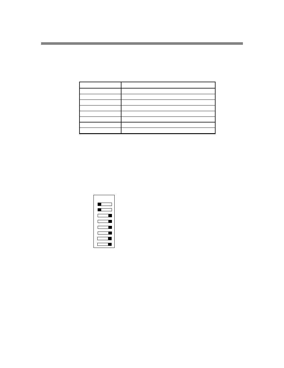
An example of setting SW1 to MB+ network node# 4 and enabling global reads plus cable-loss
checking:
OFF ON
1
2
3
4
5
6
7
8
OFF = set for node address 4
OFF = set for node address 4
ON = set for node address 4
ON = set for node address 4
ON = set for node address 4
ON = set to node address 4
ON = cable loss checking
ON = global read enabled