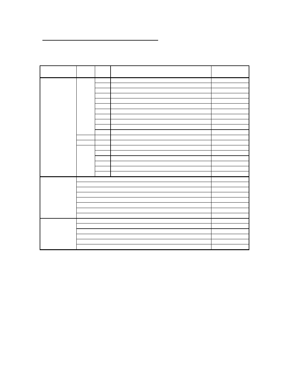
Table b-1: set up for modbus plus control – Yaskawa VS-616G5 Modbus Plus Communication Card User Manual
Page 117

Command Priority B-3
Table B-1: Set up for Modbus Plus Control
This table indicates the functions or commands that
can be accessed from Modbus Plus
, external
terminals, or the Digital Operator when the drive’s parameter b1-02 is set up for option pcb (b1-02 = 3).
The “O” indicates that the function is Operable from that source, and “n/a” indicates that the function is not
available from that source.
From
Data
Code
Bit
No.
Data Description
Function
Availability
001h
0
Forward Run/Stop
O
1
Reverse Run/Stop
O
2
multi-function input terminal 3
(2)
3
multi-function input terminal 4
(2)
4
multi-function input terminal 5
(2)
5
multi-function input terminal 6
(2)
MODBUS
6
multi-function input terminal 7
(2)
PLUS
7
multi-function input terminal 8
(2)
8
External Fault
O
9
Fault Reset
O (1)
10-15
unused
-
006h
0-15
Analog Output 1 Setting
O (6)
007h
0-15
Analog Output 2 Setting
O (7)
008h
0
Multi-function Output (terminal 9 & 10)
O (3)
1
Multi-function Output (terminal 25 & 27)
O (4)
2
Multi-function Output (terminal 26 & 27)
O (5)
3-5
unused
-
6
Fault Contact (terminal 18 & 20)
O
7
Fault Contact Closed (effective when bit 6 =1)
O
Forward Run (2 wire); Run Command (3 wire)
n/a
Reverse Run (2 wire); Stop Command (3 wire)
n/a
multi-function input terminal 3
(2)
EXTERNAL
multi-function input terminal 4
(2)
TERMINALS
multi-function input terminal 5
(2)
multi-function input terminal 6
(2)
multi-function input terminal 7
(2)
multi-function input terminal 8
(2)
Run Command
n/a
Stop Command
O (7)
DIGITAL
Reverse Run Command
n/a
OPERATOR
Local / Remote
O (10)
Jog Command
n/a
Fault Reset
O (1)
Notes:
(1) Fault Reset is only effective when run command received is “0” while in stopped condition.
(2) The availability of the multi-function input terminals vary depending upon the settings of H1-01, H1-02, H1-03, H1-04,
H1-05, H1-06 (the multi-function input settings), and A1-02 (Control Method). See the VS-616G5 Programming
Manual (YEA-TOA-S616-10.11) for more information.
(3) Effective when H2-01 is “0F”.
(4) Effective when H2-02 is “0F”.
(5) Effective when H2-03 is “0F”.
(6) Effective when H4-01 is “1F”.
(7) Effective when H4-04 is “1F”.
(8) Effective only when in the stopped condition.
(9) Effective when o2-02 is “1”.
(10) Effective when o2-01 is “1”.
