Mstr transaction #3 – Yaskawa VS-616G5 Modbus Plus Communication Card User Manual
Page 76
9-32 Examples
MSTR Transaction #3
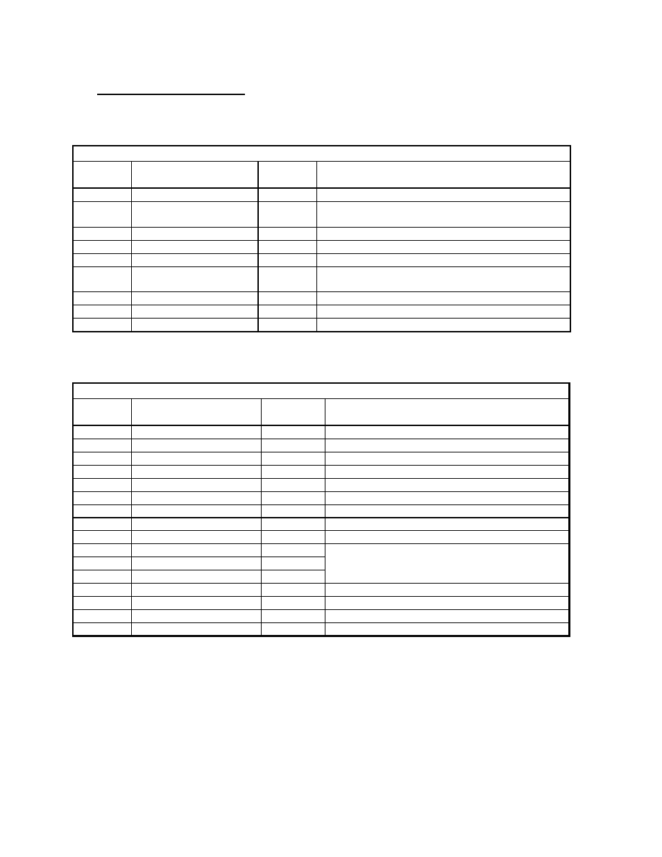
The Control Block registers for the third MSTR must be loaded with the following data before the
MSTR block is executed. This MSTR reads drive status from drive #4.
CONTROL BLOCK
Register
Number
Register
Description
Register
Data
Data
Description
40740
Operation Code
0002h
0002h = Read from Multiple Registers
40741
Network Error Code
0000h
The error code returned by Modbus Plus
communications
40742
Number of Registers
0010h
Read from 16 consecutive registers
40743
Data Register Code
F000h
F000h = Drive Status Signals
40744
Routing 1
0004h
Modbus Plus node address of the drive = 0004h
40745
Routing 2
0001h
End of routing path = 0001h (Modbus Plus
requirement)
40746
Routing 3
0000h
This routing register is not used, must be set to 0
40747
Routing 4
0000h
This routing register is not used, must be set to 0
40748
Routing 5
0000h
This routing register is not used, must be set to 0
The Data Block registers for the third MSTR will be filled with the following data after the MSTR is
completed.
DATA BLOCK
Register
Number
Register
Description
Register
Data
Data
Description
40750
Drive Status Signals
READ
RUN/STOP, FWD/REV, Drive Ready, etc.
40751
Motor Speed
READ
Motor Speed
40752
Torque Reference
READ
Torque Reference
40753
not used
n/a
n/a
40754
Speed Reference
READ
Frequency command to drive
40755
Output Frequency
READ
(0.1 Hz) Frequency at the drive
40756
Output Current
READ
Current at the output
40757
Analog Input
READ
Control Circuit Term 14 Input Volatge
40758
DC Bus Voltage
READ
(1.0 V) DC Bus voltage
40759
Fault Content 1
READ
Overcurrent, Overvoltage,
40760
Fault Content 2
READ
Drive Overload,
40761
Fault Content 3
READ
etc.
40762
Analog Input
READ
Control Circuit Term 16 Input Voltage
40763
Digital Input
READ
Input Terminal Status
40764
Analog Input
READ
Control Circuit Term 13 Input Voltage
40765
not used
n/a
n/a