H3C Technologies H3C SecBlade LB Cards User Manual
Page 13
3
•
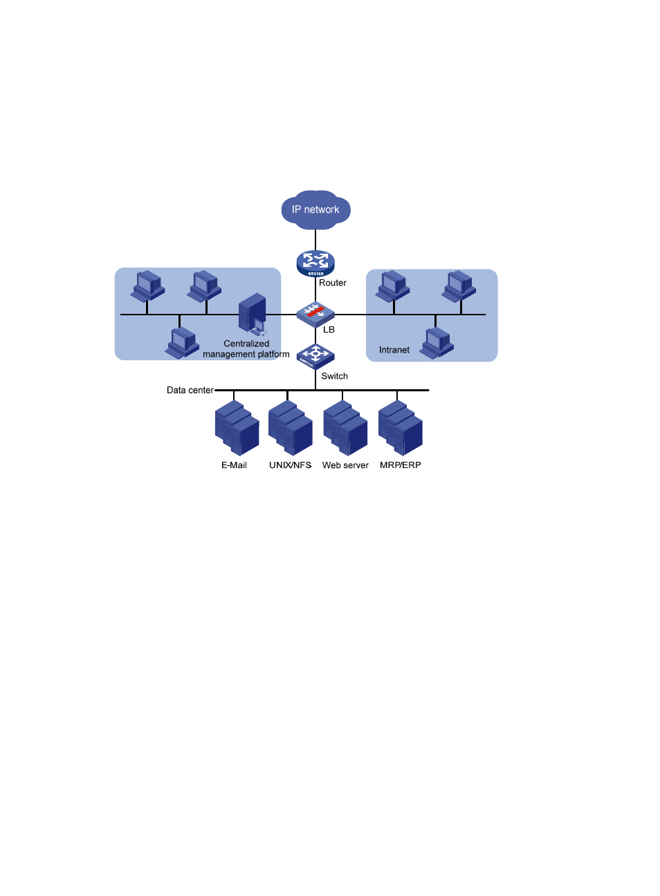
Install the LB module into the core switch. The access switch connects the server cluster to the core
switch. The LB module's IP address is used as the gateway IP address on each server and the LB
module uses NAT to achieve server load balancing.
•
Deploy the L1000-A at the data center. The access switch connects the server cluster to the L1000-A.
The L1000-A's IP address is used as the gateway IP address on each server, and the L1000-A uses
NAT to achieve server load balancing.
Figure 5 Network diagram
For link load balancing at the egress of campus networks
A campus network uses two physical links to connect to two carrier networks, ISP1 and ISP2. To
implement quick response to access requests from the internal network and optimal link selection, install
an LB product at the network egress and configure link load balancing to implement optimal link
selection based on the near-optimal or bandwidth algorithm.