H3C Technologies H3C S12500 Series Switches User Manual
Page 442
426
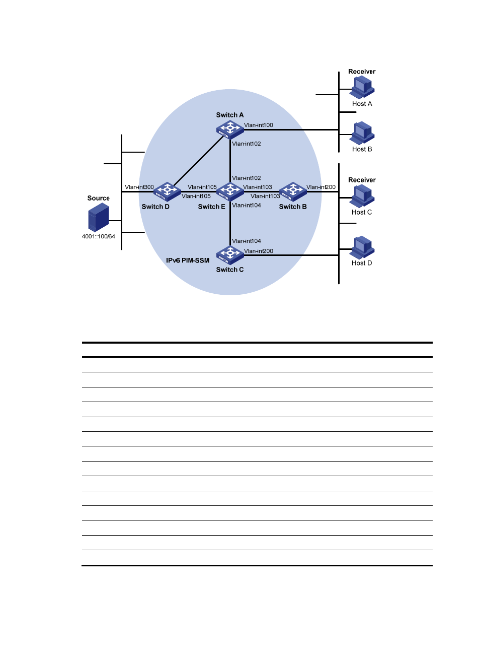
Figure 112 Network diagram
shows the interface and IPv6 address assignment, and network topology scheme.
Table 30 Interface and IPv6 address assignment
Device Interface
IPv6 address
Switch A
VLAN-interface 100
1001::1/64
Switch A
VLAN-interface 101
1002::1/64
Switch A
VLAN-interface 102
1003::1/64
Switch B
VLAN-interface 200
2001::1/64
Switch B
VLAN-interface 103
2002::1/64
Switch C
VLAN-interface 200
2001::2/64
Switch C
VLAN-interface 104
3001::1/64
Switch D
VLAN-interface 300
4001::1/64
Switch D
VLAN-interface 101
1002::2/64
Switch D
VLAN-interface 105
4002::1/64
Switch E
VLAN-interface 104
3001::2/64
Switch E
VLAN-interface 103
2002::2/64
Switch E
VLAN-interface 102
1003::2/64
Switch E
VLAN-interface 105
4002::2/64
Ether
net
E
therne
t
Ether
net
N1
N2
Vlan-
int
101
Vlan-
int10
1