Configuration procedure – H3C Technologies H3C S12500 Series Switches User Manual
Page 379
363
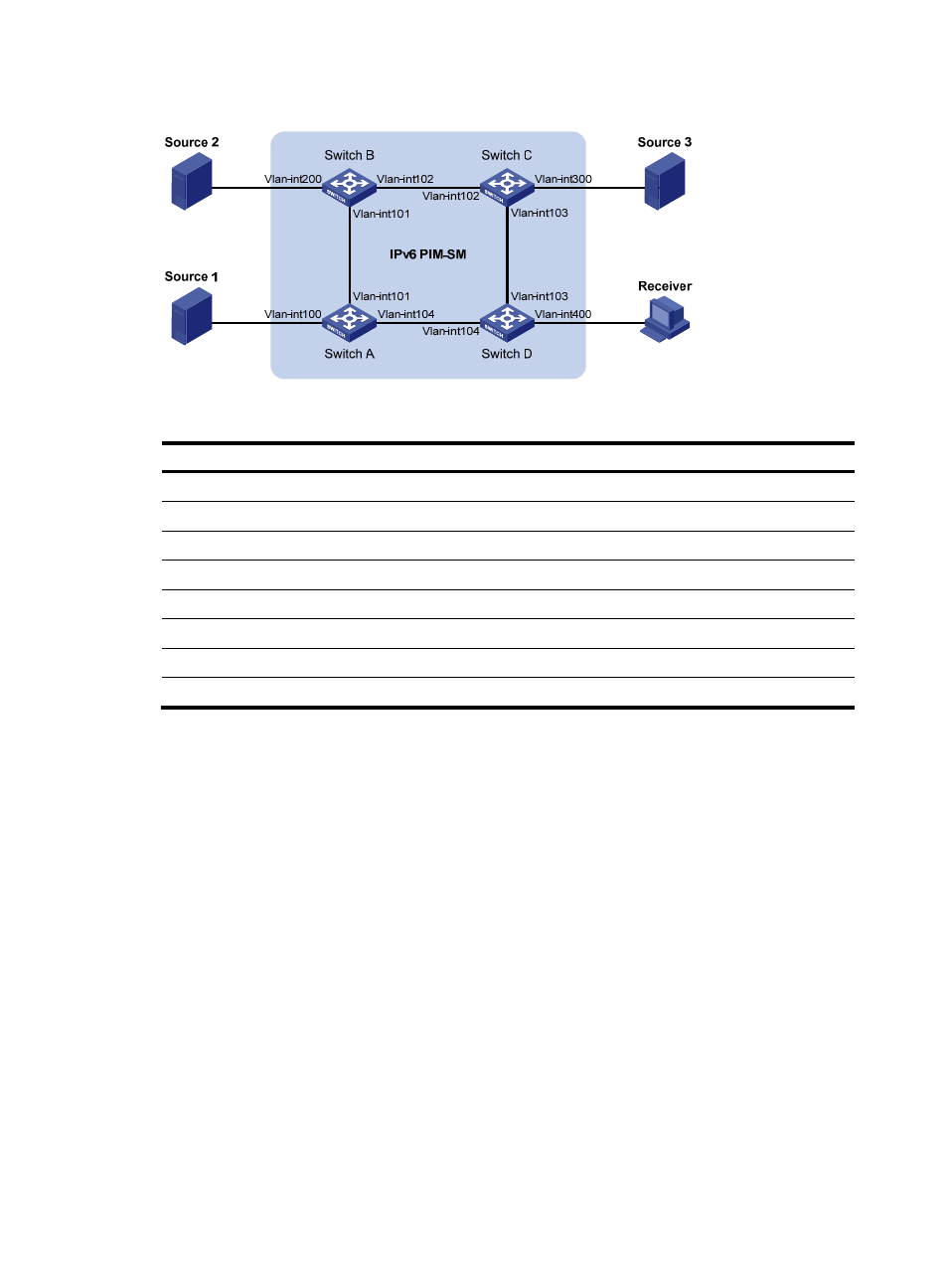
Figure 98 Network diagram
Table 24 Interface and IP address assignment
Device
Interface
IPv6 address
Device
Interface
IPv6 address
Source 1
—
1001::1/64
Source 3
—
3001::1/64
Source 2
—
2001::1/64
Receiver —
4001::1/64
Switch A
Vlan-int100 1001::2/64
Switch C
Vlan-int300
3001::2/64
Switch A
Vlan-int101
1002::1/64
Switch C
Vlan-int103 3002::1/64
Switch A
Vlan-int104 1003::1/64
Switch C
Vlan-int102 2002::2/64
Switch B
Vlan-int200 2001::2/64
Switch D
Vlan-int400
4001::2/64
Switch B
Vlan-int101
1002::2/64
Switch D
Vlan-int103
3002::2/64
Switch B
Vlan-int102
2002::1/64
Switch D
Vlan-int104
1003::2/64
Configuration procedure
1.
Enable IPv6 forwarding on each switch and configure an IPv6 address and prefix length for each
interface as shown in
2.
Configure OSPFv3 on the switches to make sure the network-layer is interoperable on the IPv6
PIM-SM domain and routing information among the switches can be dynamically updated.
(Details not shown.)
3.
Enable IPv6 multicast routing, enable IPv6 PIM-SM on each interface and enable MLD and MLD
SSM mapping on the host-side interface:
# Enable IPv6 multicast routing on Switch D, enable IPv6 PIM-SM on each interface, and enable
MLD (version 2) and MLD SSM mapping on VLAN-interface 400.
[SwitchD] multicast ipv6 routing-enable
[SwitchD] interface vlan-interface 400
[SwitchD-Vlan-interface400] mld enable
[SwitchD-Vlan-interface400] mld version 2
[SwitchD-Vlan-interface400] mld ssm-mapping enable
[SwitchD-Vlan-interface400] pim ipv6 sm
[SwitchD-Vlan-interface400] quit
[SwitchD] interface vlan-interface 103