Configuration procedure – H3C Technologies H3C S12500 Series Switches User Manual
Page 220
204
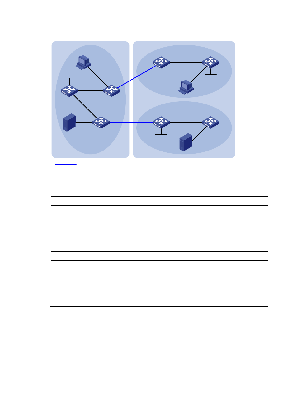
Figure 60 Network diagram
shows the interface and IP address assignment, and network topology scheme.
Table 15 Interface and IP address assignment
Device Interface IP
address
Device
Interface
IP address
Source 1
—
192.168.1.100/24
Switch D
Vlan-int105
10.110.5.1/24
Source 2
—
192.168.3.100/24
Switch D
Vlan-int103
10.110.3.2/24
Switch A
Vlan-int101
10.110.1.1/24
Switch D
Loop0
2.2.2.2/32
Switch A
Vlan-int102
10.110.2.1/24
Switch E
Vlan-int105
10.110.5.2/24
Switch A
Loop0
1.1.1.1/32
Switch E
Vlan-int300
192.168.3.1/24
Switch B
Vlan-int101
10.110.1.2/24
Switch F
Vlan-int106
10.110.6.1/24
Switch B
Vlan-int100
192.168.1.1/24
Switch F
Vlan-int104
10.110.4.2/24
Switch B
Vlan-int103
10.110.3.1/24
Switch G
Vlan-int106
10.110.6.2/24
Switch C
Vlan-int102
10.110.2.2/24
Switch G
Vlan-int400
192.168.4.1/24
Switch C
Vlan-int200
192.168.2.1/24
Switch G
Loop0
3.3.3.3/32
Switch C
Vlan-int104
10.110.4.1/24
—
—
—
Configuration procedure
1.
Configure the IP address and subnet mask for each interface as per
. (Details not shown.)
2.
Configure OSPF on the switches to make sure the network-layer is interoperable in each AS, and
routing information among the switches can be dynamically updated. (Details not shown.)
3.
Enable IP multicast routing, enable PIM-SM and IGMP, and configure a PIM-SM domain border:
# Enable IP multicast routing on Switch C, enable PIM-SM on each interface, and enable IGMP on
the host-side interface VLAN-interface 200.
Vlan-int103
Vla
n-in
t10
4
Switch B
Switch A
Source 1
AS 100
PIM-SM 1
PIM-SM 3
PIM-SM 2
Loop0
Switch D
Switch E
Switch F
Switch G
Source 2
Vlan-int102
Vl
an
-int
101
Vlan-int103
Vlan-int105
Vlan-int106
Loop0
Receiver
Receiver
Loop0
BGP peers
Vlan-
int1
01
Vlan-int105
Vlan-int106
Vl
an-
int
30
0
Vl
an-
int40
0
AS 200
Vla
n-in
t10
4
Vlan-int102
Vlan-
int2
00
Vlan-int100
Switch C