Delivery of multicast data packets – H3C Technologies H3C S12500 Series Switches User Manual
Page 264
248
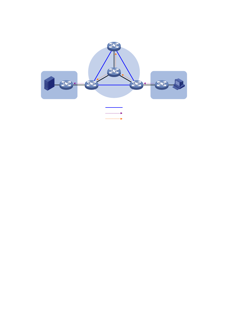
Figure 72 Transmission of multicast protocol packets
The work process of multicast protocol packets is as follows:
4.
Receiver sends an IGMP membership report for multicast group G to CE 2. CE 2 creates a local (*,
225.1.1.1) state entry and sends a join message to the VPN RP (CE 1).
5.
After receiving the join message from CE 2, the VPN instance on PE 2 creates a (*, 225.1.1.1)
state entry with the upstream interface being the MTI, and then PE 2 processes the join message.
Now, the VPN instance on PE 2 considers that the join message has been sent out of the MTI.
6.
PE 2 encapsulates the join message by means of Generic Routing Encapsulation (GRE), with its
BGP interface address as the multicast source address and the share-group address as the
multicast group address, to convert it into a normal, public network multicast data packet
(11.1.2.1, 239.1.1.1). PE 2 then forwards it to the public network.
7.
The multicast data packet (11.1.2.1, 239.1.1.1) is forwarded to the public network on all the PE
devices along the share-MDT. After receiving this packet, every PE device de-encapsulates it to turn
it back into a join message to be sent to the VPN RP. Then, each PE device checks the join message.
If any PE device finds that the VPN RP is in the site it interfaces with, it passes the join message to
the VPN instance on it. Otherwise, it discards the join message.
8.
When receiving the join message, the VPN instance on PE 1 considers that it received the message
from the MTI. PE 1 creates a local (*, 225.1.1.1) state entry, with the downstream interface being
the MTI and the upstream interface being the one that leads to CE 1. At the same time, it sends a
join message to CE 1, which is the VPN RP.
9.
After receiving the join message from the VPN instance on PE 1, CE 1 creates a local (*,
225.1.1.1) state entry or updates the entry if it already exists. By now, the construction of an RPT
across the public network is completed.
For more information about GRE, see Layer 3—IP Services Configuration Guide.
Delivery of multicast data packets
After the share-MDT is established, the multicast source forwards the VPN multicast data to the receivers
in each site along the distribution tree. The VPN multicast packets are encapsulated into public network
multicast packets on the local PE device, transmitted along the share-MDT, and then encapsulated on the
Public instance BGP peers
MD
P
PE 1
PE 2
PE 3
BGP: 11.1.2.1/24
BGP: 11.1.3.1/24
Public instance join (11.1.2.1, 239.1.1.1)
BGP: 11.1.1.1/24
Share-Group: 239.1.1.1
RP
CE 1
CE 2
Source
Receiver
G: 225.1.1.1
S: 192.1.1.1/24
VPN instance join (*, 225.1.1.1)
Site 1
Site 2