Configuration procedure – H3C Technologies H3C S12500 Series Switches User Manual
Page 251
235
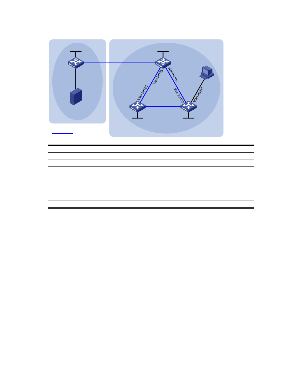
Figure 63 Network diagram
Device
Interface IP
address
Device
Interface IP
address
Source N/A
10.110.1.100/24
Switch C
Vlan-int200 10.110.2.1/24
Switch A
Vlan-int100
10.110.1.1/24
Vlan-int102 192.168.2.2/24
Vlan-int101 192.168.1.1/24
Vlan-int104 192.168.4.1/24
Loop0
1.1.1.1/32
Loop0
3.3.3.3/32
Switch B
Vlan-int101
192.168.1.2/24
Switch D
Vlan-int103 192.168.3.2/24
Vlan-int102 192.168.2.1/24
Vlan-int104 192.168.4.2/24
Vlan-int103
192.168.3.1/24
Loop0
4.4.4.4/32
Loop0
2.2.2.2/32
Configuration procedure
1.
Configure IP addresses for interfaces as shown in
. (Details not shown.)
2.
Configure OSPF. (Details not shown.)
3.
Enable IP multicast routing, PIM-SM and IGMP, and configure a PIM-SM domain border:
# Enable IP multicast routing on Switch A, and enable PIM-SM on each interface.
[SwitchA] multicast routing-enable
[SwitchA] interface vlan-interface 100
[SwitchA-Vlan-interface100] pim sm
[SwitchA-Vlan-interface100] quit
[SwitchA] interface vlan-interface 101
[SwitchA-Vlan-interface101] pim sm
[SwitchA-Vlan-interface101] quit
# Enable IP multicast routing on Switch B and Switch D in the same way as Switch A, and enable
PIM-SM on each interface.
# Enable IP multicast routing on Switch C, enable PIM-SM on each interface, and enable IGMP on
the host-side interface VLAN-interface 200.
[SwitchC] multicast routing-enable
MBGP peers
AS 100
AS 200
Source
Receiver
Switch A
Switch B
Switch C
Switch D
Vlan-int101
Vlan-int101
Vlan-int104
Vlan-int104
Vlan-int100
PIM-SM 1
PIM-SM 2
Loop0
Loop0
Loop0
Loop0